Learn how to distribute 20 satellite TV channels in both legacy 480i and HD over coax using analog NTSC and digital QAM modulators.
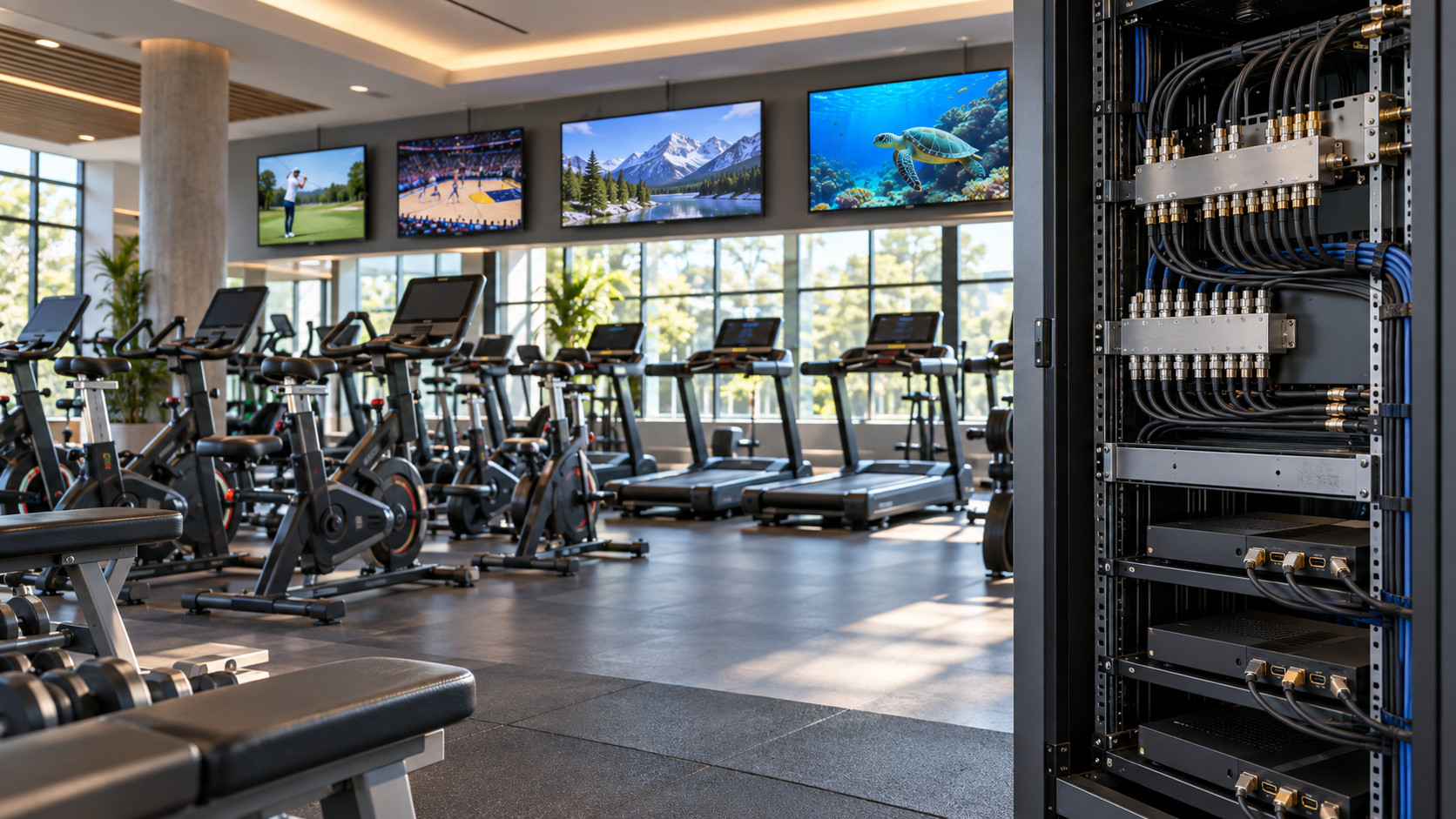
Table of Contents
A health club needed to distribute the same 20 television programs throughout a large facility, but there was an unusual requirement: some receiving equipment needed legacy 480i analog video, while newer HDTVs needed high-definition digital video up to 1080p.
The source equipment consisted of 20 satellite set-top boxes. Each receiver could provide an HDMI output for HD video while simultaneously providing composite RCA video for standard-definition 480i.
That created an important system-design question:
Can one headend generate both SD 480i and HD 1080p versions of the same 20 programs, and can both systems be distributed over the facility’s existing coax network?
The answer is yes, but the SD and HD signals need to be modulated separately.
This application is a useful example for gyms, fitness centers, hotels, hospitals, schools, senior-living facilities, correctional facilities, campuses, bars, casinos and other facilities that need to maintain legacy analog equipment while also supporting modern HDTVs.
The proposed facility had:
| Requirement | Quantity / Description |
|---|---|
| Satellite receivers | 20 Dish Network Wally receivers |
| HD source output | HDMI |
| SD source output | Composite RCA, 480i |
| Legacy exercise machines | 40 |
| Legacy required format | 480i over coax |
| HDTVs | 38 |
| Projector | 1 |
| Projector input | HDMI only |
| Number of programs | 20 |
| Existing distribution medium | 75-ohm coaxial cable |
| Desired HD distribution | Digital RF/QAM |
| Desired legacy distribution | Analog NTSC RF |
The important part is that each satellite receiver represents one television program, but that program needs to exist in two different formats.
For example:
Dish Receiver #1
HDMI → HD digital modulation → HDTVs
RCA Composite → 480i analog modulation → exercise equipment
Both outputs can originate from the same receiver, but they cannot simply be connected together. Each needs the appropriate type of RF modulator.
“We are trying to set up a 20-channel headend using twenty Dish Network Wally receivers.
They need both 480i and HDTV signals. The HDMI port outputs High Definition while the RCA composite port scales the same video down to Standard Definition 480i.
They need both signals because this will be distributed to forty pieces of exercise equipment that require 480i over coax. In addition, they have 38 HDTVs and one projector that need HD video.
Would we need to set up two headends, one for 480i and the other for 1080p, or is there an easier way?”
You need two modulation paths, because the facility needs two fundamentally different RF television formats.
That does not necessarily mean two separate equipment rooms or two completely independent distribution systems.
The equipment can be installed in the same rack.
Think of the system as:
SD Headend Path
Satellite Receiver RCA Output → Analog NTSC Modulator → Analog RF channels
and:
HD Headend Path
Satellite Receiver HDMI Output → Digital QAM Modulator → HD digital RF channels
The analog modulator creates television channels compatible with the legacy 480i equipment.
The HDMI modulator encodes the HD sources and creates digital television channels suitable for HDTVs.
A single modulator channel cannot simultaneously be both an analog 480i NTSC channel and a digital HD QAM channel. They are different television modulation systems.
Therefore, separate modulation is required.
A practical 20-channel architecture would look like this:
                         20 DISH WALLY RECEIVERS
                                  |
                +-----------------+-----------------+
                |                                   |
          HDMI OUTPUTS                        RCA OUTPUTS
                |                                   |
          DIGITAL HD PATH                     ANALOG SD PATH
                |                                   |
        THUNDER MODULATORS                  H-16RCA-RF-AMOD
                |                           + additional analog
                |                             channels if needed
          DIGITAL QAM RF                         |
                |                           ANALOG NTSC RF
                |                                   |
                +---------------+-------------------+
                                |
                        RF COMBINER / HEADEND
                                |
                     DISTRIBUTION AMPLIFIER
                         if required by loss
                                |
                           COAX NETWORK
                                |
                 +--------------+--------------+
                 |                             |
              HDTVs                   Legacy Exercise Equipment
                 |
            Clear QAM tuner
                 |
        Projector uses external
          H-STB-QAM-ATSC
There is another valid design if the building topology makes it easier:
HD QAM Headend
      |
      +----> Coax network feeding HDTVs

Analog 480i Headend
      |
      +----> Separate coax network feeding exercise machines
Both approaches can work.
This became an important question during the project.
The facility indicated that all coax lines returned to a central location and that the 40 pieces of exercise equipment requiring 480i were concentrated in one room, while the HDTVs were distributed throughout the complex.
In that situation, keeping the systems separate can actually simplify installation.
It makes RF balancing easier and keeps the legacy analog system isolated from the modern digital system.
However, analog NTSC channels and digital QAM channels can also coexist on the same coax network when engineered properly.
The requirements are straightforward:
The frequencies cannot overlap.
The RF levels need to be properly balanced.
All splitters, combiners, amplifiers and taps must support the frequency spectrum being used.
The end devices must support the modulation format of the channels they are expected to receive.
This means that one coax cable can carry many different RF carriers simultaneously.
“Thank you for confirming that the two headends are needed. I also appreciate you pointing out that they can be combined and run on one cable since the output frequencies will be different.”
Exactly.
A coaxial cable does not care whether the content is CNN, ESPN, a security camera, an analog NTSC channel, a QAM channel or an ATSC channel.
Coax is simply the transmission medium.
Think of coax as a highway.
Different RF frequencies are different lanes on that highway.
For example, one program may occupy one RF channel while another program occupies a completely different RF channel.
As long as those carriers are properly spaced and the equipment supports the frequencies being used, many programs can share the same piece of coax.
That is the fundamental principle behind cable television distribution.
“Am I explaining correctly that the 20 HD channels can be distributed over coax because they are being modulated to the same signal that High Definition off-air TV signals use? I was trying to explain it simply and want to make sure I didn’t mis-speak.”
The basic concept is correct - HD television can absolutely be distributed over coax - but there is an important distinction.
In North America, two common digital television systems are:
ATSC / 8VSB
Primarily associated with over-the-air antenna television.
and:
QAM
Primarily associated with cable television and private coax distribution systems.
For a private headend inside a gym, hotel, school or similar building where there is no need to combine the system with an off-air antenna system, Clear QAM is generally the logical choice.
So it is not that the system works simply because it is “the same signal as an off-air HD channel.”
It works because the HDMI modulator converts the HDMI source into a digital RF television signal that can travel through the coax network and be tuned by a compatible television.
The more accurate explanation is:
The HDMI sources are encoded and modulated into digital RF television channels. Those RF channels can then be distributed throughout the facility over the same type of 75-ohm coaxial infrastructure traditionally used for cable television.
For a private coax distribution network, QAM is usually preferred unless there is a specific reason to use ATSC.
With QAM, the televisions are normally configured to perform a Cable channel scan.
With ATSC, televisions normally perform an Air/Antenna channel scan.
This distinction becomes extremely important during commissioning.
A perfectly good QAM signal may appear to be “missing” if the television is accidentally scanning in Antenna mode.
Likewise, an ATSC carrier will not necessarily appear during a Cable/QAM scan.
Therefore, always verify the modulation standard and the television’s tuner mode before troubleshooting RF levels.
For the HDMI sources, a Thor Broadcast H-THUNDER HDMI RF modulator can convert HDMI video and audio into digital RF.
The H-THUNDER series supports digital modulation for private coax distribution applications, including QAM.
For a 20-source system, the modulator combination depends on the desired channel density and features.
One straightforward configuration is:
| Equipment | HDMI Inputs | Purpose |
|---|---|---|
| H-THUNDER-12 | 12 | HD programs 1–12 |
| H-THUNDER-8 | 8 | HD programs 13–20 |
| Total | 20 | 20 HD television programs |
Another configuration is:
| Equipment | HDMI Inputs |
|---|---|
| H-THUNDER-8 | 8 |
| H-THUNDER-8 | 8 |
| H-THUNDER-4 | 4 |
| Total | 20 |
The correct configuration should also take closed-captioning requirements into consideration.
The H-THUNDER-8 is the Thunder model specifically equipped with CVBS inputs that can be used for EIA-608/Line 21 closed-caption information.
Therefore, if closed captioning is important, it should be discussed during system design rather than after the equipment has been selected.
Ask:
The answers can affect the model combination selected for the headend.
The legacy exercise equipment in this project requires analog 480i television.
The Wally receiver’s composite output can feed a Thor:
H-16RCA-RF-AMOD
This unit accepts 16 independent composite video/audio sources and converts them to 16 agile analog CATV channels.
For a 20-program project, one H-16RCA unit provides 16 channels.
If the customer really needs all 20 SD programs, additional analog modulation is needed for programs 17 through 20.
If the customer can operate with only 16 programs on the exercise equipment, the second analog modulator can be eliminated.
This is an important question to ask early because many customers initially say, “We have 20 satellite boxes,” but may not actually need all 20 programs available on every legacy device.
“I always get a little confused reading the specs.
Could you give me an idea of the dB level on the outputs of these two pieces of equipment?
The Thunder specification shows an RF value in dBm, while the H-16RCA has an output listed in dBmV.
I seem to remember there is a conversion to get that into ‘cable signal’ dB.”
This is a very common source of confusion.
dBm and dBmV are not the same unit.
dBm measures absolute RF power referenced to 1 milliwatt.
dBmV measures RF voltage referenced to 1 millivolt and is commonly used in 75-ohm CATV systems.
For a 75-ohm system:
dBmV ≈ dBm + 48.75
Therefore, for example:
-35 dBm ≈ +13.75 dBmV
That is why a specification should never be interpreted simply by removing the minus sign or assuming that -35 dBm means “35 cable dB.”
For actual CATV system design, use dBmV consistently from the headend through the distribution system.
The H-16RCA-RF-AMOD is capable of approximately +53 dBmV maximum RF output and provides output adjustment.
Thor Thunder application designs commonly work around an RF output in approximately the upper-30-dBmV range.
The final value should always be confirmed from the exact model configuration and, most importantly, verified during commissioning with an RF level meter.
The analog modulator may be capable of significantly higher RF output than the digital modulator.
For example, suppose the analog carrier is around +50 dBmV while the digital carriers entering the same combiner are around the upper +30 dBmV range.
Sending those signals into the distribution network without balancing them is not good RF practice.
The analog modulator output should be attenuated so that the different carrier groups are reasonably balanced before the first major amplifier or distribution stage.
The H-16RCA provides approximately 20 dB of RF adjustment.
That allows an installer to reduce an output near +53 dBmV into approximately the mid-30-dBmV range when appropriate.
Why is that important?
A television tuner receives the entire RF spectrum.
If some carriers are dramatically stronger than others, several problems may occur.
The receiver can have difficulty maintaining reliable reception of weaker channels.
An amplifier can be driven unnecessarily hard.
Strong analog carriers can consume amplifier headroom.
The RF system can become much harder to troubleshoot.
Therefore:
Before combining different modulator systems, bring their RF carrier levels into a reasonably similar range and then design the rest of the distribution network around splitter loss, tap loss, cable loss and amplifier gain.
Assume the digital headend begins around:
+38 dBmV
Then suppose the signal passes through a combiner or splitter stage with approximately:
10 dB loss
The resulting signal becomes approximately:
+28 dBmV
If another splitter introduces 8 dB of loss:
+28 - 8 = +20 dBmV
Then suppose the coax run introduces another 6 dB:
+20 - 6 = +14 dBmV at the television
That can still be a very usable digital RF level.
The exact numbers depend on:
The correct procedure is therefore to build an RF loss budget rather than simply asking, “How many TVs can this modulator feed?”
Coaxial cable loss increases as frequency increases.
A 500-foot coax run therefore does not have one universal loss figure.
Its loss may be considerably lower at 100 MHz than at 800 MHz.
This is one reason channel planning matters.
In a large building, valuable lower-frequency spectrum can be assigned strategically to the channels for which maintaining margin is most important.
When mixing analog and digital carriers, channel placement should be planned around the actual distribution network rather than assigning frequencies randomly.
Do not think of analog channels as “using less data.”
Analog television does not work that way.
The more useful engineering concept is:
Higher RF frequencies normally experience greater coaxial attenuation, so frequency allocation should consider cable length, existing devices, amplifier bandwidth and available RF margin.
Yes.
Provided that the analog and digital modulators are assigned non-overlapping RF channels, their outputs can be combined with a properly rated passive RF combiner.
Conceptually:
DIGITAL QAM HEADEND ----\
                         >---- RF COMBINER ---- DISTRIBUTION
ANALOG NTSC HEADEND ----/
However, combining the signals is only half of the engineering work.
The installer must also verify:
A system can have plenty of signal at the headend and still fail at the last TV because 20 or 30 dB was lost through the distribution system.
Conversely, adding too much amplification can overload nearby televisions or downstream amplifiers.
More RF power is not automatically better.
Possibly, and in this particular application it may be the cleaner solution.
The customer explained that the 40 machines requiring 480i were concentrated in one area while the HDTVs were distributed throughout the facility.
If separate coax home runs are already available, the system can be designed as:
Analog Headend
      |
      +---- Exercise Room Distribution
             |
             +---- 40 legacy machines
and separately:
Digital QAM Headend
      |
      +---- Facility-Wide HD Distribution
             |
             +---- 38 HDTVs
             +---- Projector decoder
Advantages include simpler balancing, easier troubleshooting and no need to allocate analog and digital channels within one common spectrum.
But if the existing building topology makes one combined network easier, that remains a valid design as well.
“They have one projector that appears to have only an HDMI input. I can get around that by quoting the H-STB-QAM-ATSC box for use on the projector, correct?”
Correct.
The projector does not contain a QAM RF tuner, so an external tuner/decoder can be used.
The signal path becomes:
BUILDING QAM COAX
       |
       v
H-STB-QAM-ATSC
       |
       | HDMI
       v
   PROJECTOR
The H-STB-QAM-ATSC receives the clear QAM RF signal from the building coax network, tunes the desired program and outputs HDMI to the projector.
The supplied remote control is used to change channels.
This is also useful for:
The important limitation is that this decoder is intended for clear, unencrypted QAM or ATSC RF. It is not a replacement for a cable-provider box used to decrypt subscription television.
The projector itself does not change television channels.
The external H-STB-QAM-ATSC becomes the television tuner.
The user points the STB remote control at the decoder and chooses the desired RF channel.
The STB then:
The projector simply displays whatever HDMI signal the decoder provides.
No.
If the TV has a compatible clear-QAM RF tuner, coax can be connected directly to the television.
The user then runs a Cable/QAM channel scan.
An external H-STB-QAM-ATSC is required when the display does not contain the necessary tuner or when the installer wants a dedicated external tuning device.
This is increasingly important with commercial displays and certain modern monitors because not every display sold today includes a traditional television RF tuner.
Always verify the display specifications.
The source begins with the satellite receiver, but the modulator determines how that source becomes the new RF television channel.
The HDMI source supplies the original digital video and audio.
The modulator then:
The coax network then transports that RF signal throughout the building.
This leads to an important concept:
Coax does not automatically mean analog or low definition.
A properly designed coax system can carry digital HD television very effectively.
The picture quality depends on the source, encoding parameters, modulation and RF integrity - not simply on the fact that coax is being used.
This project already has coax throughout the building.
That makes RF distribution attractive because no IP switches, multicast configuration, IPTV middleware or decoder at every existing television are required.
A traditional QAM headend creates a passive TV distribution network.
The basic architecture becomes:
SOURCE
  ↓
HDMI
  ↓
QAM MODULATOR
  ↓
RF COMBINER
  ↓
COAX NETWORK
  ↓
TV RF TUNER
Once the QAM channels are on the network, every compatible television connected to that network can scan and receive them.
That can be much simpler than replacing a functioning coax infrastructure with an IPTV system solely to distribute linear television.
For a full 20-channel version of this application, a conceptual equipment list would include:
| Component | Purpose |
|---|---|
| 20 satellite/cable receivers | Program sources |
| H-THUNDER-12 + H-THUNDER-8, or equivalent 20-input Thunder combination | 20 HD HDMI programs to digital QAM RF |
| H-16RCA-RF-AMOD | First 16 SD composite programs to analog NTSC |
| Additional analog modulation for channels 17–20 | Required only if all 20 SD channels are needed |
| RF combiners | Combine modulator outputs |
| RF attenuators / level controls | Carrier balancing |
| Distribution amplifier | Added where RF-loss calculation requires it |
| CATV splitters / taps | Facility distribution |
| H-STB-QAM-ATSC | QAM-to-HDMI conversion for projector |
| 75-ohm coax | RF distribution |
| RF signal-level meter | Commissioning and troubleshooting |
The exact amplifier, tap and splitter configuration cannot be selected solely from the number of televisions.
It must be based on the physical coax layout.
Once the equipment is installed, commission the system logically.
First configure every source receiver and verify HDMI and composite output.
Then configure the analog channels.
Next configure the digital QAM channels.
Make sure there are no frequency conflicts.
Measure RF output from each headend.
Balance the analog and digital carrier groups before combining them.
Measure the output after the combiner.
Check the input to the first distribution amplifier.
Measure the closest outlet.
Measure the furthest outlet.
Perform QAM channel scans on multiple television models.
Verify legacy analog reception on the exercise machines.
Verify the external H-STB-QAM-ATSC on the projector.
Finally, document the channel lineup and RF frequencies for future service.
A customer may report:
“The TVs receive some channels perfectly, but other channels are missing.”
Do not immediately assume the modulator is bad.
One of the first things to check is RF level across the spectrum.
If one headend is entering the distribution system at +50 dBmV while another group of carriers is significantly lower, the imbalance may cause reception problems.
Also check frequency-dependent cable loss.
If channels at the low end of the spectrum work while high-frequency channels fail at distant locations, excessive high-frequency coax loss may be involved.
The RF meter should be used at:
That shows exactly where the signal is being lost.
One of the best ways to explain the system to a customer is:
“Coax is just copper. What matters is what RF signal we place onto that copper.”
The headend determines:
The coax network simply transports those RF carriers from the headend to the televisions.
That is why the same building coax infrastructure can potentially carry analog NTSC, digital QAM, ATSC or other RF services - assuming the components and receiving devices support the chosen standards.
Can HDMI be distributed over existing coax?
Yes. An HDMI RF modulator converts an HDMI source into a television RF channel that can be transported over a 75-ohm coaxial distribution network.
Is HDMI actually traveling through the coax?
No. HDMI is the input to the modulator. The modulator encodes the HDMI audio/video and creates a new RF television signal. That RF signal travels through the coax.
Can 1080p video travel over coax?
Yes. Digital RF television systems can transport HD programming over coax. The source encoding, modulator configuration and television compatibility determine the usable format.
Can analog NTSC and digital QAM channels share one coax cable?
Yes, provided the frequencies do not conflict, RF levels are properly balanced and the distribution components support the required spectrum.
Should a private gym use QAM or ATSC?
For a closed building coax system that is not being combined with an off-air antenna system, Clear QAM is generally a practical choice in North America.
What is the difference between QAM and ATSC?
QAM is commonly used for cable television and private CATV networks. ATSC 8VSB is primarily associated with terrestrial over-the-air television in North America.
Can one modulator output both analog 480i and digital HD from one program?
Not in the configuration described here. Separate analog and digital modulation paths are used.
Can the same satellite receiver feed both systems?
Yes, if the receiver provides simultaneous HDMI and composite outputs. HDMI feeds the HD modulator while composite video/audio feeds the analog modulator.
What if a display has HDMI but no coax input?
Use an external RF tuner/decoder such as the H-STB-QAM-ATSC. It receives clear QAM or ATSC RF and converts the selected channel to HDMI.
How does the user change channels on a projector?
The remote control for the external RF decoder changes the channel. The projector remains on its HDMI input.
Do I always need a distribution amplifier?
No. Amplification depends on the RF loss budget. Short networks with limited splitting may not require amplification, while larger systems normally do.
Is a stronger RF signal always better?
No. Too little signal causes reception problems, but excessive signal can overload tuners and amplifiers. Proper RF engineering requires maintaining signals inside a useful operating window.
Why should analog and digital carrier levels be similar?
Large differences between carrier levels can reduce system margin and create tuner or amplifier problems. Balancing the signals before the main distribution system makes the network more predictable.
No. They are different RF measurements. In a 75-ohm system, approximately:
dBmV = dBm + 48.75
Always use consistent units when calculating a CATV RF budget.
Can I determine the complete system just from the number of TVs?
No. The number of outlets is only one factor. Cable length, cable type, splitter loss, tap loss, frequency, amplifier placement and building topology are equally important.
This health-club application demonstrates why modern RF-over-coax systems can be extremely flexible.
The customer did not need to replace the existing coax infrastructure simply because some endpoints required analog 480i while others required HD.
Instead, the same 20 program sources could be processed in two ways:
Composite outputs → analog NTSC modulation for legacy equipment
and:
HDMI outputs → digital Clear QAM modulation for HDTVs
The resulting RF networks could either remain separate or be combined onto one properly engineered coax distribution system.
The key is not simply choosing a modulator.
A reliable installation requires proper planning of:
Once those items are engineered correctly, one centralized headend can distribute dozens of television programs throughout a large facility using simple, reliable coaxial infrastructure.

 EN
EN