A technical guide to HDMI-to-RF modulation: encoding, MPEG-TS, ATSC/QAM/DVB-T, coax planning, and stable in-building TV channels.
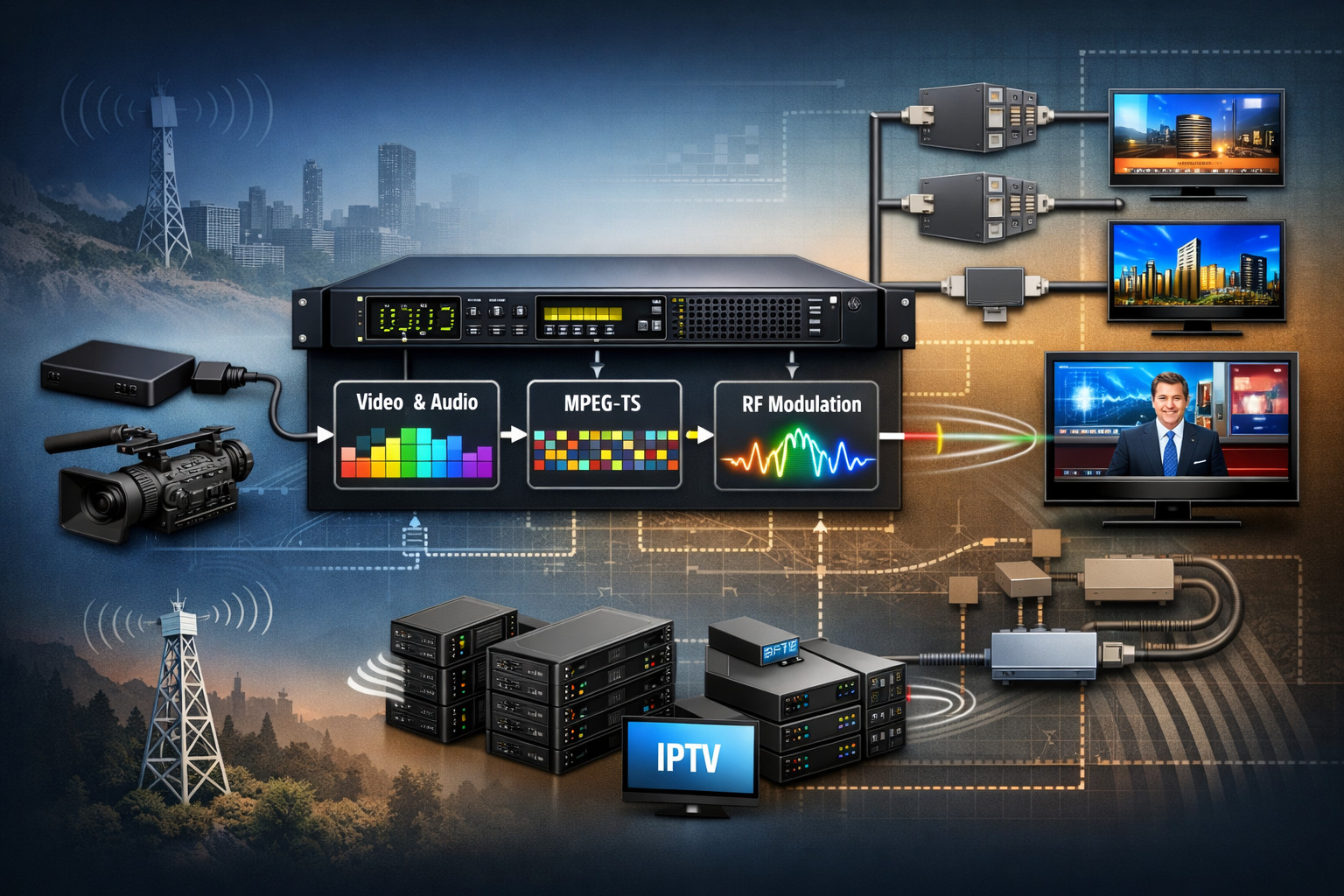
Table of Contents
HDMI RF modulation is the headend process of taking a baseband HDMI program (video + audio), encoding it into a broadcast-style transport stream, and modulating that stream onto one or more RF carriers so the content can be injected into a coaxial distribution network and tuned on TVs like a regular channel.
In practice, the device doing this work is usually an encoder-modulator: it combines real-time compression (for example MPEG-2 or H.264 depending on the platform), MPEG transport stream packetization, program/service signaling, and RF modulation (QAM/DVB-C, ATSC, DVB-T, ISDB-T, etc.). Thor Broadcast’s HDMI-to-RF product families are built around this integrated workflow, ranging from compact single-program units to higher-density multi-input chassis systems that can also output IPTV streams in parallel.
An HDMI signal is baseband: it carries uncompressed (or lightly encoded) video timing plus audio and auxiliary data over TMDS signaling. That is fundamentally different from what a TV tuner expects on coax, where the tuner locks to a radio-frequency carrier and demodulates a digital multiplex. The HDMI-to-RF modulator bridges these worlds by executing four stages that must all be correct for the channel to be stable on every television in the building.
First, the modulator must reliably acquire the HDMI input timing and audio mode. In real installations this is not trivial, because HDMI sources can change format based on EDID negotiation and can renegotiate after power events. A well-behaved headend keeps HDMI cable runs short, mechanically secure, and consistent, then uses a modulator platform designed for managed distribution rather than living-room display interconnect. For compact deployments where you want to keep the headend simple, Thor offers small HDMI RF units such as the Petit HDMI RF Modulator, which is commonly used when a single HDMI source needs to appear as one or more RF channels on coax.
Second, the modulator encodes the baseband audio/video into a compressed elementary stream. The encoder settings determine picture quality, channel-change behavior, and end-to-end latency. Shorter GOP structures generally improve channel acquisition and error recovery but consume more bitrate for the same subjective quality. Rate control determines whether the output behaves like a constant-rate broadcast transport, which is helpful when the downstream modulator expects a stable payload rate.
Third, the device packetizes the encoded essence into an MPEG Transport Stream (MPEG-TS), creating the signaling tables that receivers depend on to identify programs, audio/video PIDs, and service metadata. Even in a closed coax plant, disciplined service signaling matters because consumer televisions can be surprisingly strict; small mistakes in PSI/PSIP or timing (PCR) behavior can manifest as intermittent audio loss, black frames, or channels that disappear after rescans.
Fourth, the modulator maps the transport stream into symbols and places those symbols on an RF carrier that fits a defined channel bandwidth and frequency plan. The carrier is then injected into the coax plant, combined with other carriers (and sometimes with off-air signals), and distributed through splitters, taps, and amplifiers to every outlet. At the endpoint, the television’s tuner repeats the chain in reverse: lock carrier, demodulate symbols, recover TS, decode audio/video, and present the program.
The modulation standard is not an abstract checkbox; it determines which tuners can lock your signal and how much bitrate you can carry per RF channel at a given robustness. QAM (in cable ecosystems, including DVB-C/J.83 variants) is often chosen for dense in-building lineups where high throughput per 6/7/8 MHz channel is valuable. ATSC 8-VSB is typically chosen where TVs and set-top boxes expect ATSC channels and scanning behavior aligns with ATSC service conventions. DVB-T is common in terrestrial DVB regions and is valued for its resilience characteristics in certain RF environments because it is OFDM-based.
For HDMI RF modulation projects, the practical question is simple: what do your televisions support in their built-in tuners? If the receiving fleet is mixed, you must design around the least-capable or least-flexible endpoints. In many hospitality and enterprise deployments, selecting a modulator that supports the required standard and allows disciplined control of service metadata is the difference between a stable channel lineup and constant support tickets.
Thor’s HDMI-to-coax families cover these real-world needs with multiple standard options depending on model. If your design is multi-source and you want an integrated platform that can encode and modulate multiple HDMI inputs while also offering IPTV outputs, a headend chassis such as 1-4 HDMI to QAM Modulators and IPTV Streaming Encoders illustrates the combined “encode + transport + RF” architecture that is common in modern coax plants.
HDMI RF modulation succeeds or fails on RF link margins, not on whether the picture looks good when directly connected via HDMI. In coax digital TV, the tuner needs adequate modulation quality to recover symbols, which is commonly assessed via MER (Modulation Error Ratio) and BER (Bit Error Rate). A system can appear “almost fine” yet collapse under small environmental changes if MER margins are thin, connectors are poor, or amplifiers are driven into distortion.
The headend modulator must generate a clean carrier with stable output power, but the distribution network often decides whether outlets remain decodable. Every splitter introduces insertion loss; long coax runs add frequency-dependent attenuation; unterminated branches and poor connectors introduce reflections that reduce MER; and over-amplification can create intermodulation products that corrupt multiple channels. This is why RF level planning should be done end-to-end, from modulator output to the farthest outlet, including all passives, taps, patch panels, and any active amplification stages.
In most installations you will combine multiple internally generated RF channels and distribute them through a structured splitter tree. Thor provides coax distribution building blocks intended for these plants, such as Coax Multiplexers / Splitters / Combiners, which are typically used to assemble and fan out carrier lineups inside a facility.
Commissioning should validate RF performance at representative outlets, not only at the rack. When the RF plant is engineered correctly, televisions lock quickly, channels remain present after rescans, and long-duration playback stays stable without macroblocking bursts or audio dropouts.
An HDMI modulator is effectively a broadcast encoder with an RF output stage, so classic broadcast compression rules apply. If you allocate too little bitrate to a high-motion program, blocking and smear will be visible on large displays even if RF lock is perfect. If you set a very long GOP to chase bitrate efficiency, some televisions may take longer to present video after a channel change, and error recovery can be slower after transient RF disturbances. If you run an unusual resolution or frame rate, some TVs may fail to decode entirely even though the channel appears in the scan list.
The practical target is consistency: standardize on a small set of resolutions and frame rates that match your content and your TV fleet, then choose a bitrate that fits the RF capacity while preserving acceptable quality. Many coax plants optimize for predictable capacity per RF channel rather than absolute quality per program, because the goal is often “many channels everywhere” with minimal operational friction. This is where integrated multi-input platforms can help, because they let you manage encoding and RF parameters consistently across multiple services from one interface rather than tuning a collection of unrelated devices.
If you need multiple HDMI sources converted into a stable RF lineup, Thor’s multi-input HDMI modulator families-such as 1-8 HDMI Digital RF Modulator CC and modular rack approaches like the HDMI RF Modulator Chassis System (1-12 units) are commonly selected to keep those parameters standardized and maintainable at scale.
In an in-building coax system, you are effectively operating a miniature cable system. That means you need a channel plan: which RF channel frequencies you will use, how they map to service numbers on televisions, and how you will prevent collisions with any existing signals on the coax (including off-air feeds, legacy modulators, or upstream services). A sloppy plan leads to ghost channels, disappearing services, and rescans that reorder lineups unpredictably.
Two layers must be aligned. The first is the RF layer: carriers must be placed in valid channel bandwidths with sufficient guard margins and within the frequency response of your distribution components. The second is the service layer: the transport stream must present stable program/service identifiers and, where relevant, virtual channel mapping so that TVs show the channels in a predictable way. Receivers cache this information; if you change it casually, you create long-tail problems where some TVs show the “old” service while others show the “new” one until each set is manually rescanned.
The safest operational approach is to treat channel plan changes like configuration management: document the lineup, keep service IDs stable, and change only one variable at a time. Thor’s managed HDMI modulator platforms are typically used in this disciplined way, especially in hospitality and enterprise environments where the cost of touching every television is much higher than the cost of careful headend planning.
HDMI RF modulation is often assumed to be “near real-time,” but end-to-end latency is an engineering outcome, not a guarantee. Delay is dominated by encoder buffering (lookahead, rate control), GOP structure, transport buffering, and the television’s own decode and presentation pipeline. Two TVs receiving the same RF channel can show different latency simply due to differences in internal processing.
If you are distributing live events where viewers can see both the real world and the screens, you should validate delay empirically. Use a test pattern with a running clock or timecode and measure the source versus displayed time. Then tune encoder settings on the modulator platform where possible. The goal is not “zero latency” but stable, predictable latency that does not drift or jump after reboots and that stays within your operational tolerance.
Compact HDMI modulators can be suitable for these scenarios when engineered carefully, but the broader point remains: choose a platform that gives you control and stability, and verify with the exact TVs you will deploy, because the endpoint often dominates perceived delay.
A single HDMI-to-RF modulator is an excellent solution for one program-such as a lobby channel, a signage feed, or a single camera output-distributed across a facility. As soon as you have multiple sources, the economics and maintainability change. A pile of unrelated single-channel devices increases cabling complexity and multiplies failure points, while also making it harder to keep encoding settings and RF output levels consistent across the lineup.
At modest channel counts, a modular chassis that physically organizes multiple HDMI RF modulators can reduce risk simply by improving power, cooling, cable strain relief, and configuration discipline. Thor’s HDMI RF Modulator Chassis System (1-12 units) represents this “organized density” approach where the headend can be expanded predictably without turning the rack into a patchwork.
When you want true integrated management-multiple HDMI inputs, centralized multiplexing control, RF outputs, and often IPTV outputs for monitoring or secondary distribution-an integrated encoder-modulator chassis becomes attractive. Thor’s multi-input families, including 1-8 HDMI Digital RF Modulator CC and the mixed RF/IP headend concept shown in 1-4 HDMI to QAM Modulators and IPTV Streaming Encoders, are typically used when the system needs to behave like an engineered headend rather than a collection of converters.
The “HDMI side” of an HDMI RF modulation system is where many real-world failures originate. Sources reboot, firmware updates change output behavior, someone swaps a set-top box, or an HDMI cable gets tugged during unrelated maintenance. Because the RF network faithfully distributes whatever the modulator outputs, a small upstream disturbance can become a facility-wide outage.
Stability comes from reducing variables. Keep HDMI cable lengths short and consistent, and physically secure them. Standardize the HDMI source output mode where possible rather than letting devices auto-negotiate. Use headend platforms that support network management so you can verify input status and configuration quickly. Then validate recovery behavior: power-cycle the source and the modulator, simulate cable disconnects, and ensure the system returns to stable output without manual intervention. These steps are far more predictive of long-term success than any single headline specification.
Thor’s HDMI modulator ecosystem is frequently deployed in precisely these managed environments, which is why the product family spans compact single-channel units for simple channel injection and higher-density platforms for centralized control and repeatable configuration.
HDMI RF modulation is the most direct way to turn an HDMI program into a tunable coax TV channel, but the outcome depends on more than the modulator itself. You must align modulation standard with endpoint tuner capability, choose encoding settings that receivers handle reliably, build a disciplined channel plan, and engineer the coax plant so MER and BER margins remain healthy at every outlet. When those pieces are treated as one system, HDMI-to-RF distribution becomes a stable, broadcast-like service inside your facility.
Thor Broadcast’s product lineup supports this system approach, from compact HDMI modulators like the Petit HDMI RF Modulator, to higher-density multi-input platforms such as the 1-8 HDMI Digital RF Modulator CC, and scalable rack organization via the HDMI RF Modulator Chassis System. Use the platform class that matches your channel count and operational discipline, then validate with real TVs and real coax runs before you declare the project complete.
FCC: Interference rejection thresholds of consumer DTV receivers (PDF)
FCC: Office of Engineering and Technology
MIT: TMDS encoding notes (Part 1)
MIT: TMDS encoding notes (Part 2)
University of Maryland: Fundamentals of QAM (PDF)
NTIA: report referencing ATSC 8-VSB RF transmission (PDF)

 EN
EN

