| Disponibilidad: | Check availability | Condición: | nuevo |
|
| Envío: | a partir de $0.00 | Garantía: | 2Yrs |
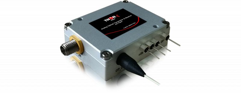
Conjunto mini transmisor y receptor de fibra óptica para banda Ku de 18GHz.
El transmisor puede aceptar señales RF desde 10MHz hasta 18GHz, señales analógicas o digitales moduladas en RF, y convertirlas en luz modulada ópticamente; el receptor convierte la señal óptica de nuevo en una señal eléctrica RF.
Existen muchos desafíos para enviar RF de alta frecuencia a través de cable coaxial de cobre a larga distancia; el TX/RX de banda Ku permite enviar esta señal por fibra desde 0 hasta 40 km, si es necesario.
La conversión eléctrica a óptica es transparente, independiente del protocolo o modulación; funcionan con estándares de modulación analógica o digital.
Se utiliza para aplicaciones en banda C, banda L, banda Ku, banda S satelital, comunicación móvil 5G/4G/3G, DAS o radar.
aplicaciones:
Comunicación móvil 5G/4G/3G
Remoto de antenas
Comunicación satelital
Transporte de señal GPS
Transporte de señal de pulso
Sistema de antena distribuida
Pruebas y mediciones de alta velocidad
Distribución de señal de video en nodos HFC y FTTx
Comunicación inalámbrica de banda ancha
Transmisión OFDM por fibra
Radar por fibra
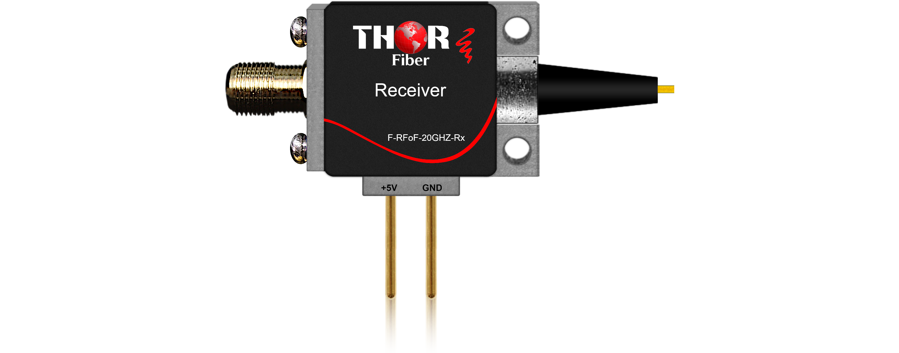
Receptor:
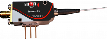
Transmisor:
F-RFoF-18GHZ-Tx Transmisor de fibra óptica de 18 GHz
F-RFoF-18GHZ-Rx Receptor de fibra óptica de 18 GHz
| Parámetro | Símbolo | Condición | Mín. | Máx. | Unidad |
| Temperatura de operación | Topr | -40 | -40 | +70 | °C |
| Temperatura de almacenamiento | Tstg | -40 | +85 | °C | |
| Potencia de entrada de saturación | Ps | -- | 10 | mW | |
| Corriente directa | If | -- | 10 | mA | |
| Polarización inversa | Vr | PD | -- | 20 | V |
| Voltaje de operación DC | Vd | Pin +5V | +4.7 | +5.5 | V |
| Corriente oscura | Id | -- | 10 | nA | |
| Humedad relativa | Hr | -- | 95 | % | |
| Presión | Pr | 86 | 106 | kPa | |
| ESD | Modelo cuerpo humano | -- | Clase 1B |
Características eléctricas y ópticas del receptor
| Parámetro | Símbolo | Condición de prueba | Mín | Típ. | Máx | Unidad |
| Rango de longitud de onda | l | 800 | -- | 1650 | nm | |
| Responsividad | R | 1310nm | 0.7 | 0.8 | -- | mA/mW |
| 1550nm | 0.7 | 0.85 | -- | |||
| Ancho de banda de frecuencia | BW | RCC | 0.01 | -- | 6 | GHz |
| RXC | 0.01 | -- | 12 | |||
| RUC | 0.01 | -- | 18 | |||
| RKC | 0.01 | -- | 24 | |||
| Ondulación de la banda pasante | Planitud | RCC,0.1GHz~6GHz | -- | +1 | +1.2 | dB |
| RXC,0.1GHz~12GHz | -- | +1.2 | +1.5 | |||
| RUC,0.1GHz~18GHz | -- | +1.5 | +2 | |||
| RKC,1GHz~24GHz | -- | +1.7 | +2.5 | |||
| Pérdida de retorno RF | RL | RCC,0.1GHz~6GHz | -- | -12 | -9 | dB |
| RCC,0.1GHz~6GHz | -- | -10 | -7 | |||
| RCC,0.1GHz~6GHz | -- | -10 | -5 | |||
| RKC 0.1GHz~18GHz | -- | -10 | -5 | |||
| RKC 18GHz~24GHz | -- | -5 | -3 | |||
| Reflexión trasera | ORL | PD | -- | -35 | -- | dB |
| Corriente oscura | Id | PD | -- | 5 | 10 | nA |
| Voltaje de operación | Vd | Pin +5V | +4.8 | +5 | +5.2 | V |
| Consumo de energía | Pdiss | Fuente de alimentación +5V | -- | 25 | 50 | mW |
Especificación de fibra del receptor
| Parámetro | Típ. | Unidad |
| Tipo de fibra | Monomodo | |
| Tipo de conector óptico | FC/APC | |
| Longitud del pigtail | 1 | m |
| Radio mínimo de curvatura | 30-2 | mm |
Función de pines del receptor
| PIN | Nombre | Dirección | Nota |
| 1 | GND | I | GND |
| 2 | +5V | I | Alimentación DC +5V |
| 3 | RF | O | Salida RF, SMA hembra, 50Ohm |
Valores absolutos máximos del transmisor
| Parámetro | Símbolo | Condición | Mín. | Máx. | Unidad |
| Temperatura de operación | Topr | Temperatura de carcasa | -40 | +70 | °C |
| Temperatura de almacenamiento | Tstg | -40 | +85 | °C | |
| Voltaje de operación DC | Vd | -5V | -5.5 | -4.7 | V |
| +5V | +4.7 | +5.5 | |||
| Potencia de entrada RF | Prf | Continuo | -- | 20 | dBm |
| Humedad relativa | Hr | 10 | 95 | % | |
| Presión atmosférica | Pr | 86 | 106 | kPa | |
| ESD | Modelo cuerpo humano | -- | Clase 1A |
Especificación típica del transmisor (CWDM)
| Parámetro | Condición de prueba | Mín. | Típ. | Máx. | Unidad |
| Rango de frecuencia | TSC | 0.01 ~ 3 | GHz | ||
| TCC | 0.01 ~ 6 | ||||
| TXC | 0.01 ~ 12 | ||||
| TYC | 0.01 ~ 16 | ||||
| TUC | 0.01 ~ 18 | ||||
| Longitud de onda óptica | l0 es la longitud de onda estándar CWDM | Opcional | nm | ||
| Rango de longitud de onda óptica | Rango de temperatura de operación | l0-3 | l0 | l0+3 | nm |
| Potencia óptica de salida | +25 | -- | 9 | -- | dBm |
| Ganancia (1) | Rango de temperatura de operación | -30 | -26 | -- | dB |
| Planitud de ganancia | TSC 100MHz ~ 3GHz | -- | +1.5 | +2 | dB |
| TCC 100MHz ~ 6GHz | -- | +1.5 | +2.5 | ||
| TXC 100MHz ~ 12GHz | -- | +2 | +3 | ||
| TYC 100MHz ~ 16GHz | -- | +2 | +2.5 | ||
| TUC 100MHz ~ 18GHz | -- | +2 | +3 | ||
| Pérdida de retorno RF | TSC 100MHz ~ 3GHz | -- | -15 | -10 | dB |
| TCC 100MHz ~ 6GHz | -- | -10 | -5 | ||
| TXC 100MHz ~ 12GHz | -- | -10 | -5 | ||
| TYC 100MHz ~ 16GHz | -- | -12 | -10 | ||
| TUC 100MHz ~ 18GHz | -- | -10 | -5 | ||
| Entrada P-1dB | 1GHz | -- | 18 | -- | dBm |
Hoja de datos del transmisor
| Parámetro | Condición de prueba | Mín. | Típ. | Máx. | Unidad | ||
| SFDR (1) | TSC | 1GHz | 114 | 119 | -- | dB- Hz2/3 | |
| 2GHz | 112 | 116 | -- | ||||
| 3GHz | 107 | 111 | -- | ||||
| TCC | 1GHz | 110 | 118 | -- | |||
| 3GHz | 105 | 112 | -- | ||||
| 6GHz | 101 | 106 | -- | ||||
| TXC | 1GHz | 1270nm/1370nm | 110 | 118 | -- | ||
| 1530nm/1550nm | 108 | 114 | -- | ||||
| 6GHz | 1270nm/1370nm | 102 | 110 | -- | |||
| 1530nm/1550nm | 102 | 108 | -- | ||||
| 12GHz | 1270nm/1370nm | 98 | 106 | -- | |||
| 1530nm/1550nm | 94 | 100 | |||||
| TYC | 1GHz | 110 | 116 | -- | |||
| 10GHz | 105 | 112 | -- | ||||
| 16GHz | 100 | 106 | -- | ||||
| TUC | 1GHz | 108 | 114 | -- | |||
| 10GHz | 102 | 108 | -- | ||||
| 18GHz | 97 | 103 | -- | ||||
| IIP3 (1) | TSC | 1GHz | 32 | 36 | -- | dBm | |
| 2GHz | 30 | 33 | -- | ||||
| 3GHz | 27 | 30 | -- | ||||
| TCC | 1GHz | 27 | 34 | -- | |||
| 2GHz | 25 | 31 | -- | ||||
| 6GHz | 22 | 26 | -- | ||||
| TXC | 1GHz | 27 | 33 | -- | |||
| 2GHz | 24 | 30 | -- | ||||
| 12GHz | 21 | 26 | -- | ||||
| TYC | 1GHz | 28 | 32 | -- | |||
| 10GHz | 25 | 30 | -- | ||||
| 16GHz | 22 | 26 | -- | ||||
| TUC | 1GHz | 28 | 32 | -- | |||
| 10GHz | 25 | 30 | -- | ||||
| 18GHz | 22 | 27 | -- | ||||
| Figura de ruido (1) | TSC | 1GHz | -- | 31 | 34 | dB | |
| 2GHz | -- | 33 | 36 | ||||
| 3GHz | -- | 37 | 40 | ||||
| TCC | 1GHz | -- | 31 | 36 | |||
| 3GHz | -- | 36 | 41 | ||||
| 6GHz | -- | 40 | 44 | ||||
| TXC | 1GHz | -- | 31 | 36 | |||
| 1530nm/1550nm | -- | 35 | 39 | ||||
| 6GHz | -- | 39 | 44 | ||||
| 1530nm/1550nm | -- | 41 | 45 | ||||
| 12GHz | -- | 41 | 47 | ||||
| 1530nm/1550nm | -- | 49 | 53 | ||||
| TYC | 1GHz | -- | 32 | 37 | |||
| 10GHz | -- | 36 | 41 | ||||
| 16GHz | -- | 40 | 45 | ||||
| TUC | 1GHz | -- | 34 | 39 | |||
| 10GHz | -- | 41 | 46 | ||||
| 18GHz | -- | 46 | 50 | ||||
| Corriente de operación | +5V | -- | 65 | 800 | mA | ||
| -5V | -- | 70 | 100 | ||||
| Voltaje de operación | +5V | +4.8 | +5 | +5.2 | VDC | ||
| -5V | -5.2 | -5 | -4.8 | ||||
Hoja de datos del transmisor
| Parámetro | Condición de prueba | Mín. | Típ. | Máx. | Unidad | |
| Planitud de ganancia | TSC | 100MHz ~ 3GHz | -- | +/-1.5 | +/-2 | dB |
| TCC | 100MHz ~ 6GHz | -- | +/-1.5 | +/-2.5 | ||
| TXC | 100MHz ~ 12GHz | -- | +/-2 | +/-3 | ||
| Pérdida de retorno RF | TSC | 100MHz ~ 3GHz | -- | -13 | -10 | |
| TCC | 100MHz ~ 6GHz | -- | -12 | -10 | ||
| TXC | 100MHz ~ 12GHz | -- | -10 | -8 | ||
| Entrada P-1dB | 1GHz | -- | 18 | -- | dBm | |
| SFDR (2) | TSC | 1GHz | 112 | 118 | -- | dB- Hz2/3 |
| 2GHz | 110 | 115 | -- | |||
| 3GHz | 108 | 113 | -- | |||
| TCC | 1GHz | 112 | 118 | -- | ||
| 3GHz | 108 | 113 | -- | |||
| 6GHz | 102 | 107 | -- | |||
| TXC | 1GHz | 108 | 114 | -- | ||
| 6GHz | 101 | 106 | -- | |||
| 12GHz | 95 | 99 | -- | |||
| IIP3 (2) | TSC | 1GHz | 33 | 38 | -- | dBm |
| 2GHz | 31 | 35 | -- | |||
| 3GHz | 29 | 33 | -- | |||
| TCC | 1GHz | 33 | 38 | -- | ||
| 3GHz | 29 | 33 | -- | |||
| 6GHz | 22 | 27 | -- | |||
| TXC | 1GHz | 28 | 33 | -- | ||
| 6GHz | 24 | 28 | -- | |||
| 12GHz | 20 | 23 | -- | |||
| Figura de ruido (2) | TSC | 1GHz | -- | 35 | 38 | dB |
| 2GHz | -- | 36 | 39 | |||
| 3GHz | -- | 37 | 40 | |||
| TCC | 1GHz | -- | 35 | 38 | ||
| 3GHz | -- | 37 | 40 | |||
| 6GHz | -- | 40 | 43 | |||
| TXC | 1GHz | -- | 36 | 39 | ||
| 6GHz | -- | 43 | 46 | |||
| 12GHz | -- | 48 | 51 | |||
| Parámetro | Condición de prueba | Mín. | Típ. | Máx. | Unidad |
| Corriente de operación | +5V | -- | 65 | 800 | mA |
| -5V | -- | 70 | 100 | ||
| Voltaje de operación | +5V | +4.8 | +5 | +5.2 | VDC |
| -5V | -5.2 | -5 | -4.8 |
Conector del transmisor
| Tipo | Conector | |
| RF | TSC | SMA, 50Ohm, hembra |
| TCC | SMA, 50Ohm, hembra | |
| TXC | SMA, 50Ohm, hembra | |
| TYC | Tipo K (2.92mm, 50Ohm), hembra | |
| TUC | Tipo K (2.92mm, 50Ohm), hembra | |
| Óptico | FC/APC (3) | |
| Tipo de fibra óptica | SMF-28 (Estándar) (3) | |
| Alimentación |
Filtro paso bajo EMI, condensador de paso, la temperatura de soldadura no debe exceder 300 °C y 3s |
|
Función de pines
| PIN | Nombre | Dirección | Nota |
| 1 | +5V | I | Alimentación DC +5V |
| 2 | -5V | I | Alimentación DC -5V |
| 3 | GND | I | GND |
| 4 | OP | O |
Monitor de potencia óptica, nivel TTL, nivel bajo (<0.4V) indica potencia óptica baja, nivel alto (+5V) indica potencia óptica normal. |
Tabla de números de código de longitud de onda de banda C ITU
| xx | Frecuencia (THz) |
Longitud de onda central (nm) |
xx | Frecuencia | Longitud de onda central (nm) |
| 17 | 191.7 | 1563.86 | 37 | 193.7 | 1547.72 |
| 18 | 191.8 | 1563.05 | 38 | 193.8 | 1546.92 |
| 19 | 191.9 | 1562.23 | 39 | 193.9 | 1546.12 |
| 20 | 192.0 | 1561.42 | 40 | 194.0 | 1545.32 |
| 21 | 192.1 | 1560.61 | 41 | 194.1 | 1544.53 |
| 22 | 192.2 | 1559.79 | 42 | 194.2 | 1543.73 |
| 23 | 192.3 | 1558.98 | 43 | 194.3 | 1542.94 |
| 24 | 192.4 | 1558.17 | 44 | 194.4 | 1542.14 |
| 25 | 192.5 | 1557.36 | 45 | 194.5 | 1541.35 |
| 26 | 192.6 | 1556.55 | 46 | 194.6 | 1540.56 |
| 27 | 192.7 | 1555.75 | 47 | 194.7 | 1539.77 |
| 28 | 192.8 | 1554.94 | 48 | 194.8 | 1538.98 |
| 29 | 192.9 | 1554.13 | 49 | 194.9 | 1538.19 |
| 30 | 193.0 | 1553.33 | 50 | 195.0 | 1537.40 |
| 31 | 193.1 | 1552.52 | 51 | 195.1 | 1536.61 |
| 32 | 193.2 | 1551.72 | 52 | 195.2 | 1535.82 |
| 33 | 193.3 | 1550.92 | 53 | 195.3 | 1535.04 |
| 34 | 193.4 | 1550.12 | 54 | 195.4 | 1534.25 |
| 35 | 193.5 | 1549.32 | 55 | 195.5 | 1533.47 |
| 36 | 193.6 | 1548.51 | 56 | 195.6 | 1532.68 |
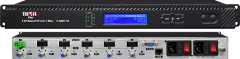 Extensor por Fibra Óptica para 6 Canales L-Band Satelital 54-3000 MHz - CWDM
Extensor por fibra óptica para 6 canales de LNB satelital. Sistema de transmisión por fibra óptica para 6 señales de antena satelital LNB con óptica CWDM interna. Ideal para transporte punto a punto o para sistemas de distribución LTTH a pequeña escala (solo Nivel 1) con 32 o menos receptores ópticos. Soporta señal ATSC desde antena local off-air, 54-3000 MHz. Mejor sistema de distribución satelital para unidades de vivienda múltiple (MDU).
 RF de 6 GHz por fibra
Transporte óptico de RF analógica de hasta 6 GHz - Transmisor/Receptor de RF por fibra para aplicaciones de transporte RF Satcom, GPS, WiMAX, LTE y DAS
 EN
EN


