| Availability: | Check availability | Condition: | new |
|
| Shipping: | starting at $0.00 | Warranty: | 2Yrs |
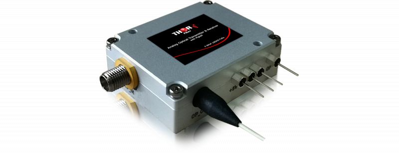
18GHz Ku-Band fiber optic mini transmitter and receiver set.
The transmitter is able to accept RF signals from 10MHz to 18GHz analog or digital RF-modulated signals and convert them to optically modulated light; and the receiver converts the optical signal back to an electrical RF signal.
There are a lot of challenges to sending high-frequency RF over long-distance coaxial copper cable; the K-Band TX/RX allows you to send this signal over fiber from 0 to 40Km, if needed.
Electrical to optical conversion is transparent, protocol- or modulation-independent; they work with analog or digital modulation standards.
Used for C-band, L-band, Ku-band, S-band satellite, cell phone 5G/4G/3G mobile communication, DAS, or radar applications.
Applications:
5G/4G/3G Mobile Communication
Antenna remoting
Satellite communication
GPS signal transport
Pulse signal transport
Distributed antenna system
High-speed test and measurement
Video signal distribution in HFC and FTTx nodes
Wideband wireless communication
OFDM fiber transmission
Radar over fiber
Receiver:
Transmitter:
F-RFoF-18GHZ-Tx 18 GHz fiber optic Transmitter
F-RFoF-18GHZ-Rx 18 GHz fiber optic Receiver
| Parameter | Symbol | Condition | Min. | Max. | Unit |
| Operating Temperature | Topr | -40 | -40 | +70 | deg C |
| Storage Temperature | Tstg | -40 | +85 | deg C | |
| Saturation Input Power | Ps | -- | 10 | mW | |
| Forward Current | If | -- | 10 | mA | |
| Reverse Bias | Vr | PD | -- | 20 | V |
| DC Operating Voltage | Vd | +5V pin | +4.7 | +5.5 | V |
| Dark Current | Id | -- | 10 | nA | |
| Relative Humidity | Hr | -- | 95 | % | |
| Pressure | Pr | 86 | 106 | kPa | |
| ESD | Human body model | -- | Class 1B |
Receiver Electrical and Optical Characteristics
| Parameter | Symbol | Test Condition | Min | Typ. | Max | Unit |
| Wavelength Range | l | 800 | -- | 1650 | nm | |
| Responsivity | R | 1310nm | 0.7 | 0.8 | -- | mA/mW |
| 1550nm | 0.7 | 0.85 | -- | |||
| Frequency Bandwidth | BW | RCC | 0.01 | -- | 6 | GHz |
| RXC | 0.01 | -- | 12 | |||
| RUC | 0.01 | -- | 18 | |||
| RKC | 0.01 | -- | 24 | |||
| Ripple of Passband | Flatness | RCC,0.1GHz~6GHz | -- | +1 | +1.2 | dB |
| RXC,0.1GHz~12GHz | -- | +1.2 | +1.5 | |||
| RUC,0.1GHz~18GHz | -- | +1.5 | +2 | |||
| RKC,1GHz~24GHz | -- | +1.7 | +2.5 | |||
| RF Return Loss | RL | RCC,0.1GHz~6GHz | -- | -12 | -9 | dB |
| RCC,0.1GHz~6GHz | -- | -10 | -7 | |||
| RCC,0.1GHz~6GHz | -- | -10 | -5 | |||
| RKC 0.1GHz~18GHz | -- | -10 | -5 | |||
| RKC 18GHz~24GHz | -- | -5 | -3 | |||
| Back Reflection | ORL | PD | -- | -35 | -- | dB |
| Dark Current | Id | PD | -- | 5 | 10 | nA |
| Operating Voltage | Vd | +5V Pin | +4.8 | +5 | +5.2 | V |
| Power Consumption | Pdiss | +5V power supply | -- | 25 | 50 | mW |
Receiver Fiber Specification
| Parameter | Typ. | Unit |
| Fiber Type | Single Mode | |
| Optical Connector Type | FC/APC | |
| Pigtail Length | 1 | m |
| Minimum Bend Radius | 30-2 | mm |
Receiver PIN Function
| PIN | Name | Direction | Note |
| 1 | GND | I | GND |
| 2 | +5V | I | +5V DC Power |
| 3 | RF | O | RF Out, SMA Female, 50Ohm |
Transmitter Absolute Maximum Ratings
| Parameter | Symbol | Condition | Min. | Max. | Unit |
| Operating Temperature | Topr | Case temperature | -40 | +70 | deg C |
| Storage Temperature | Tstg | -40 | +85 | deg C | |
| DC Operating Voltage | Vd | -5V | -5.5 | -4.7 | V |
| +5V | +4.7 | +5.5 | |||
| RF Input Power | Prf | Continuous | -- | 20 | dBm |
| Relative Humidity | Hr | 10 | 95 | % | |
| Atmospheric Pressure | Pr | 86 | 106 | kPa | |
| ESD | Human body model | -- | Class1A |
Transmitter Typical Specification (CWDM)
| Parameter | Test Condition | Min. | Typ. | Max. | Unit |
| Frequency Range | TSC | 0.01 ~ 3 | GHz | ||
| TCC | 0.01 ~ 6 | ||||
| TXC | 0.01 ~ 12 | ||||
| TYC | 0.01 ~ 16 | ||||
| TUC | 0.01 ~ 18 | ||||
| Optical Wavelength | l0 is the standard CWDM wavelength | Optional | nm | ||
| Optical Wavelength Range | Operating Temperature Range | l0-3 | l0 | l0+3 | nm |
| Output Optical Power | +25 | -- | 9 | -- | dBm |
| Gain (1) | Operating Temperature Range | -30 | -26 | -- | dB |
| Gain Flatness | TSC 100MHz ~ 3GHz | -- | +1.5 | +2 | dB |
| TCC 100MHz ~ 6GHz | -- | +1.5 | +2.5 | ||
| TXC 100MHz ~ 12GHz | -- | +2 | +3 | ||
| TYC 100MHz ~ 16GHz | -- | +2 | +2.5 | ||
| TUC 100MHz ~ 18GHz | -- | +2 | +3 | ||
| RF Return Loss | TSC 100MHz ~ 3GHz | -- | -15 | -10 | dB |
| TCC 100MHz ~ 6GHz | -- | -10 | -5 | ||
| TXC 100MHz ~ 12GHz | -- | -10 | -5 | ||
| TYC 100MHz ~ 16GHz | -- | -12 | -10 | ||
| TUC 100MHz ~ 18GHz | -- | -10 | -5 | ||
| Input P-1dB | 1GHz | -- | 18 | -- | dBm |
Transmitter Data Sheet
| Parameter | Test Condition | Min. | Typ. | Max. | Unit | ||
| SFDR (1) | TSC | 1GHz | 114 | 119 | -- | dB- Hz2/3 | |
| 2GHz | 112 | 116 | -- | ||||
| 3GHz | 107 | 111 | -- | ||||
| TCC | 1GHz | 110 | 118 | -- | |||
| 3GHz | 105 | 112 | -- | ||||
| 6GHz | 101 | 106 | -- | ||||
| TXC | 1GHz | 1270nm?1370nm | 110 | 118 | -- | ||
| 1530nm/1550nm | 108 | 114 | -- | ||||
| 6GHz | 1270nm?1370nm | 102 | 110 | -- | |||
| 1530nm/1550nm | 102 | 108 | -- | ||||
| 12GHz | 1270nm?1370nm | 98 | 106 | -- | |||
| 1530nm/1550nm | 94 | 100 | |||||
| TYC | 1GHz | 110 | 116 | -- | |||
| 10GHz | 105 | 112 | -- | ||||
| 16GHz | 100 | 106 | -- | ||||
| TUC | 1GHz | 108 | 114 | -- | |||
| 10GHz | 102 | 108 | -- | ||||
| 18GHz | 97 | 103 | -- | ||||
| IIP3 (1) | TSC | 1GHz | 32 | 36 | -- | dBm | |
| 2GHz | 30 | 33 | -- | ||||
| 3GHz | 27 | 30 | -- | ||||
| TCC | 1GHz | 27 | 34 | -- | |||
| 2GHz | 25 | 31 | -- | ||||
| 6GHz | 22 | 26 | -- | ||||
| TXC | 1GHz | 27 | 33 | -- | |||
| 2GHz | 24 | 30 | -- | ||||
| 12GHz | 21 | 26 | -- | ||||
| TYC | 1GHz | 28 | 32 | -- | |||
| 10GHz | 25 | 30 | -- | ||||
| 16GHz | 22 | 26 | -- | ||||
| TUC | 1GHz | 28 | 32 | -- | |||
| 10GHz | 25 | 30 | -- | ||||
| 18GHz | 22 | 27 | -- | ||||
| Noise Figure (1) | TSC | 1GHz | -- | 31 | 34 | dB | |
| 2GHz | -- | 33 | 36 | ||||
| 3GHz | -- | 37 | 40 | ||||
| TCC | 1GHz | -- | 31 | 36 | |||
| 3GHz | -- | 36 | 41 | ||||
| 6GHz | -- | 40 | 44 | ||||
| TXC | 1GHz | 1270nm/1370nm | -- | 31 | 36 | ||
| 1530nm/1550nm | -- | 35 | 39 | ||||
| 6GHz | 1270nm/1370nm | -- | 39 | 44 | |||
| 1530nm/1550nm | -- | 41 | 45 | ||||
| 12GHz | 1270nm/1370nm | -- | 41 | 47 | |||
| 1530nm/1550nm | -- | 49 | 53 | ||||
| TYC | 1GHz | -- | 32 | 37 | |||
| 10GHz | -- | 36 | 41 | ||||
| 16GHz | -- | 40 | 45 | ||||
| TUC | 1GHz | -- | 34 | 39 | |||
| 10GHz | -- | 41 | 46 | ||||
| 18GHz | -- | 46 | 50 | ||||
| Operating Current | +5V | -- | 65 | 800 | mA | ||
| -5V | -- | 70 | 100 | ||||
| Operating Voltage | +5V | +4.8 | +5 | +5.2 | VDC | ||
| -5V | -5.2 | -5 | -4.8 | ||||
Transmitter Data Sheet
| Parameter | Test Condition | Min. | Typ. | Max. | Unit | |
| Gain Flatness | TSC | 100MHz ~ 3GHz | -- | +/-1.5 | +/-2 | dB |
| TCC | 100MHz ~ 6GHz | -- | +/-1.5 | +/-2.5 | ||
| TXC | 100MHz ~ 12GHz | -- | +/-2 | +/-3 | ||
| RF Return Loss | TSC | 100MHz ~ 3GHz | -- | -13 | -10 | |
| TCC | 100MHz ~ 6GHz | -- | -12 | -10 | ||
| TXC | 100MHz ~ 12GHz | -- | -10 | -8 | ||
| Input P-1dB | 1GHz | -- | 18 | -- | dBm | |
| SFDR (2) | TSC | 1GHz | 112 | 118 | -- | dB- Hz2/3 |
| 2GHz | 110 | 115 | -- | |||
| 3GHz | 108 | 113 | -- | |||
| TCC | 1GHz | 112 | 118 | -- | ||
| 3GHz | 108 | 113 | -- | |||
| 6GHz | 102 | 107 | -- | |||
| TXC | 1GHz | 108 | 114 | -- | ||
| 6GHz | 101 | 106 | -- | |||
| 12GHz | 95 | 99 | -- | |||
| IIP3 (2) | TSC | 1GHz | 33 | 38 | -- | dBm |
| 2GHz | 31 | 35 | -- | |||
| 3GHz | 29 | 33 | -- | |||
| TCC | 1GHz | 33 | 38 | -- | ||
| 3GHz | 29 | 33 | -- | |||
| 6GHz | 22 | 27 | -- | |||
| TXC | 1GHz | 28 | 33 | -- | ||
| 6GHz | 24 | 28 | -- | |||
| 12GHz | 20 | 23 | -- | |||
| Noise Figure (2) | TSC | 1GHz | -- | 35 | 38 | dB |
| 2GHz | -- | 36 | 39 | |||
| 3GHz | -- | 37 | 40 | |||
| TCC | 1GHz | -- | 35 | 38 | ||
| 3GHz | -- | 37 | 40 | |||
| 6GHz | -- | 40 | 43 | |||
| TXC | 1GHz | -- | 36 | 39 | ||
| 6GHz | -- | 43 | 46 | |||
| 12GHz | -- | 48 | 51 | |||
| Parameter | Test Condition | Min. | Typ. | Max. | Unit |
| Operating Current | +5V | -- | 65 | 800 | mA |
| -5V | -- | 70 | 100 | ||
| Operating Voltage | +5V | +4.8 | +5 | +5.2 | VDC |
| -5V | -5.2 | -5 | -4.8 |
Transmitter Connector
| Type | Connector | |
| RF | TSC | SMA, 50Ohm, Female |
| TCC | SMA, 50Ohm, Female | |
| TXC | SMA, 50Ohm, Female | |
| TYC | K Type (2.92mm, 50Ohm), Female | |
| TUC | K Type (2.92mm, 50Ohm), Female | |
| Optical | FC/APC (3) | |
| Optical Fiber Type | SMF-28 (Standard) (3) | |
| Power |
EMI Low Pass Filter, Feed Through Capacitor, Soldering Temperature Should Not Exceed 300 deg C and 3s |
|
PIN Function
| PIN | Name | Direction | Note |
| 1 | +5V | I | +5V DC Power |
| 2 | -5V | I | -5V DC Power |
| 3 | GND | I | GND |
| 4 | OP | O |
Optical Power Monitor, TTL Level, Low Level(<0.4V) is Optical Power Low, High Level(+5V) is Optical Power Normal. |
ITU C band Wavelength Code Number Table
| xx | Frequency (THz) |
Center Wavelength (nm) |
xx | Frequency | Center Wavelength (nm) |
| 17 | 191.7 | 1563.86 | 37 | 193.7 | 1547.72 |
| 18 | 191.8 | 1563.05 | 38 | 193.8 | 1546.92 |
| 19 | 191.9 | 1562.23 | 39 | 193.9 | 1546.12 |
| 20 | 192.0 | 1561.42 | 40 | 194.0 | 1545.32 |
| 21 | 192.1 | 1560.61 | 41 | 194.1 | 1544.53 |
| 22 | 192.2 | 1559.79 | 42 | 194.2 | 1543.73 |
| 23 | 192.3 | 1558.98 | 43 | 194.3 | 1542.94 |
| 24 | 192.4 | 1558.17 | 44 | 194.4 | 1542.14 |
| 25 | 192.5 | 1557.36 | 45 | 194.5 | 1541.35 |
| 26 | 192.6 | 1556.55 | 46 | 194.6 | 1540.56 |
| 27 | 192.7 | 1555.75 | 47 | 194.7 | 1539.77 |
| 28 | 192.8 | 1554.94 | 48 | 194.8 | 1538.98 |
| 29 | 192.9 | 1554.13 | 49 | 194.9 | 1538.19 |
| 30 | 193.0 | 1553.33 | 50 | 195.0 | 1537.40 |
| 31 | 193.1 | 1552.52 | 51 | 195.1 | 1536.61 |
| 32 | 193.2 | 1551.72 | 52 | 195.2 | 1535.82 |
| 33 | 193.3 | 1550.92 | 53 | 195.3 | 1535.04 |
| 34 | 193.4 | 1550.12 | 54 | 195.4 | 1534.25 |
| 35 | 193.5 | 1549.32 | 55 | 195.5 | 1533.47 |
| 36 | 193.6 | 1548.51 | 56 | 195.6 | 1532.68 |
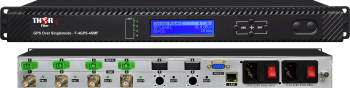 4 GPS signals over the Fiber TX/RX with Outdoor Waterproof Enclosure
4 GPS RF carrier signals over 4 fibers Outdoor waterproof enclosure optical transmitter and 19" rack-mountable receiver with redundant power supply
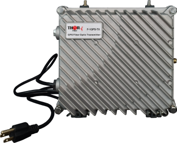 GPS over Fiber - Reference Timing Fiber Optic Waterproof Solution
Waterproof outdoor GPS fiber optic transmitter and 19" rack-mountable receiver; sends the signal from a GPS antenna to a receiver over singlemode fiber. The transmitter and receiver have RF and optical meters, allowing quick and seamless implementation without any optical or RF instruments.
 ES
ES


