Fix Web NMS access on H-IRD-V3-ATSC-2, then cut latency via encoder tuning. Learn why PTS stays mandatory and what’s controllable.
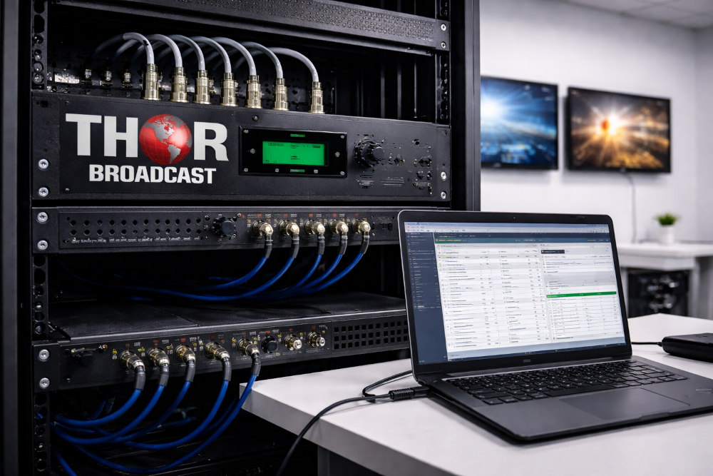
Table of Contents
The client deployed the Thor Broadcast H-IRD-V3-ATSC-2 Receiver / Modulator for a low-latency broadcast processing application.
Primary requirements:
Reliable access to Web NMS (management interface)
Stable ATSC demodulation and processing
Minimize end-to-end latency
Evaluate timing and buffer behavior
Investigate advanced control (API / automation)
Web interface did not load
Default IP address timed out
Device powered and connected correctly
Subnet mismatch between PC and IRD
The management port (NMS) requires the PC to be on the same IP subnet as the device. The browser timeout was caused by network layer mismatch, not device failure.
Steps taken:
Verified NMS port connection
Confirmed device power and link
Checked PC IP configuration
Added matching subnet to PC
Access restored successfully
Result: Full Web GUI control restored without hardware intervention.
The deployment required minimum processing delay. The client investigated whether timing model (PTS/DTS) could be modified.
| Question | Result |
|---|---|
| Remove PTS compliance? | ❌ Not possible |
| Per-stream PTS control? | ❌ Not supported |
| Alternative latency reduction? | ✔ Yes (encoder side) |
PTS (Presentation Time Stamp) is required for:
A/V synchronization
Decoder buffer control
MPEG transport stability
Clock reference alignment
Removing it would cause:
Video/audio drift
Buffer underflow/overflow
Decoder crashes
Therefore PTS is mandatory by MPEG design.
Since IRD timing must remain compliant, latency is reduced at the encoder side.
| Parameter | Recommended Setting | Effect |
|---|---|---|
| GOP Size | 12–15 (short GOP) | Lower decode delay |
| B-Frames | 0 | Eliminates frame reordering |
| Encoding Mode | IP / IBP | Faster decode |
| Bitrate Mode | CBR | Stable buffering |
| PCR Stability | Clean & consistent | Reduces IRD buffering |
Result: Significant latency improvement without breaking MPEG compliance.
The client requested:
API control
Network automation
External integration
| Feature | Availability |
|---|---|
| REST API | ❌ Not available |
| SNMP | ❌ Not available |
| Remote Protocol | ❌ Not available |
| Web GUI | ✔ Supported |
| Front Panel | ✔ Supported |
The IRD is designed for manual GUI-based management, not automated control.
Most “device not responding” cases are subnet mismatches, not hardware failure.
Low latency must be achieved without breaking PTS/DTS.
The IRD is mostly deterministic — the encoder determines delay.
Clean streams = less IRD buffering = lower latency.
ATSC RF → H-IRD-V3-ATSC-2 → Processing / Modulation → Distribution
             │
             └── Web NMS (Same Subnet Required)
✔ Broadcast-grade ATSC demodulation
✔ Stable MPEG timing compliance
✔ Deterministic processing delay
✔ Reliable GUI control
✔ Suitable for professional broadcast chains
✘ No API / automation
✘ Latency tuning limited to encoder side
✘ Requires correct subnet configuration
✘ PTS cannot be bypassed
Low-latency broadcast monitoring
Contribution receive → modulation
ATSC demodulation for processing chains
RF to transport conversion
Studio receive and rebroadcast
The H-IRD-V3-ATSC-2 proved stable and suitable for low-latency operation once network configuration was corrected. While MPEG timing compliance prevents disabling PTS, careful encoder tuning significantly reduces delay. The system provides reliable broadcast performance, though it is designed for manual control rather than automated API-based environments.
Below is a full engineering network diagram for the H-IRD-V3-ATSC-2 IRD system, focused on real deployment (RF → IRD → processing/modulation → distribution + NMS control).
                     ┌────────────────────────┐
                     │      ATSC RF Source    │
                     │  (OTA Antenna / Feed) │
                     └───────────┬────────────┘
                                 │ 75Ω Coax
                                 ▼
                    ┌────────────────────────────┐
                    │     H-IRD-V3-ATSC-2        │
                    │  ATSC Receiver / Processor │
                    │                            │
                    │  RF IN → ATSC Demod        │
                    │  MPEG TS Processing        │
                    │  A/V Decode / Remux        │
                    │                            │
                    │  Outputs:                  │
                    │  • ASI / IP / RF (model)   │
                    │  • Video / Audio           │
                    │                            │
                    │  Management: NMS (Web GUI) │
                    └───────┬───────────┬────────┘
                            │           │
                            │           │
                Transport / Output      │ NMS (Management)
                            │           │
                            ▼           ▼
              ┌────────────────────┐   ┌────────────────────┐
              │  Downstream System │   │  Engineering Laptop │
              │ (Modulator / IPTV /│   │  Same Subnet Req.   │
              │  Encoder / Router) │   │  Web Browser (GUI)  │
              └──────────┬─────────┘   └──────────┬─────────┘
                         │                        │
                         ▼                        ▼
                 ┌──────────────┐         ┌──────────────┐
                 │ Distribution │         │ Local Switch │
                 │ RF / IP / ASI│         │ (Same VLAN)  │
                 └──────┬───────┘         └──────────────┘
                        │
                        ▼
                 ┌──────────────┐
                 │ End Devices  │
                 │ TV / STB /   │
                 │ Monitoring   │
                 └──────────────┘
ATSC antenna or RF feed enters H-IRD-V3-ATSC-2
IRD demodulates RF → MPEG Transport Stream
Internal decode / remux / processing occurs
Depending on configuration, IRD outputs to:
RF modulator chain
IPTV / IP network
ASI transport systems
Monitoring / decode outputs
This becomes the broadcast processing stage.
Web interface requires:
PC connected to NMS port
PC and IRD on same subnet
Example:
| Device | IP |
|---|---|
| IRD | 192.168.1.168 |
| Laptop | 192.168.1.10 |
If subnet mismatch → Web GUI timeout (most common issue).
Latency is influenced mainly by encoder upstream, not IRD.
Recommended upstream encoder settings:
Short GOP (12–15)
B-frames = 0
Stable PCR
CBR bitrate
Clean RF signal
ATSC Antenna
   ↓
H-IRD-V3-ATSC-2
   ↓
IP / RF Modulator
   ↓
Distribution Network
   ↓
TVs / Monitoring / Processing
NMS runs in parallel management network, not media path.
Same subnet for NMS access
Stable RF signal
Clean MPEG transport
Proper grounding / RF quality
Managed switch
Dedicated engineering VLAN
Static IP for IRD
Shielded RF cables
| Issue | Cause |
|---|---|
| Cannot open Web GUI | Subnet mismatch |
| High latency | Encoder configuration |
| Video glitches | Weak RF / bad PCR |
| Buffer instability | Dirty transport stream |

 ES
ES

