Learn how to send 8 HD-TVI cameras and RS-485 PTZ control over one multimode fiber link in an industrial CCTV system.
Application Example - Industrial CCTV System Over Multimode Fiber
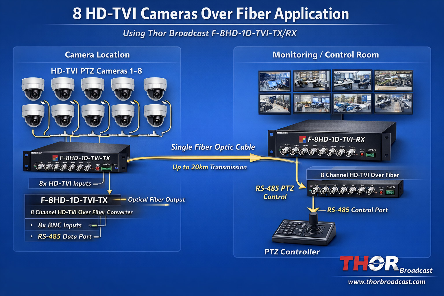
Table of Contents
In many industrial environments such as plants, factories, or large facilities, cameras may be located hundreds of feet away from the monitoring location. Running new coax cables for each camera can be expensive and time-consuming, especially if fiber infrastructure already exists between buildings or control rooms.
A practical solution is to use a TVI over Fiber transmitter and receiver kit, which allows multiple HD analog cameras to be transported over a single fiber optic link.
In this example, we will explain how to transmit:
8 HD-TVI cameras
PTZ control signals using RS-485
Over an existing multimode fiber cable
Main Components
8 HD-TVI Cameras (PTZ capable)
8-Channel TVI Fiber Transmitter
Fiber Optic Cable (Multimode or Single Mode)
8-Channel TVI Fiber Receiver
DVR / Control System
RS-485 PTZ Controller
Each camera outputs a TVI video signal over coax.
Example formats:
720p
1080p
HD-TVI analog signal
These signals connect to the 8 BNC inputs on the fiber transmitter.
The transmitter performs optical multiplexing:
All 8 camera signals are combined into one optical stream.
The signal is converted into laser light.
This optical signal is then transmitted through a single fiber strand.
The signal travels through the existing fiber cable.
Typical distances:
Multimode fiber: hundreds of meters to several kilometers
Single mode fiber: up to tens of kilometers
In this example:
Distance = ~500 ft
Multimode fiber = works well for short runs
At the monitoring location:
The fiber receiver converts the optical signal back into 8 coax TVI outputs.
Each output connects to:
DVR
Video matrix
Encoder
Monitor system
Many CCTV PTZ cameras use RS-485 serial communication for control.
Examples of PTZ commands:
Pan left/right
Tilt up/down
Zoom
Presets
The fiber system includes a return data channel.
This means:
Control signals can travel from the control room back to the cameras.
| Signal | Direction |
|---|---|
| Video | Cameras → Control Room |
| PTZ Control | Control Room → Cameras |
The fiber unit provides one RS-485 interface, even though there are 8 cameras. This works because RS-485 is a multi-drop bus. Multiple devices share the same communication line.
Each PTZ camera has a unique address (ID).
Example configuration:
| Camera | Address |
|---|---|
| Camera 1 | 001 |
| Camera 2 | 002 |
| Camera 3 | 003 |
| Camera 4 | 004 |
| Camera 5 | 005 |
| Camera 6 | 006 |
| Camera 7 | 007 |
| Camera 8 | 008 |
When the controller sends a command:
Example command:
Camera Address: 003
Command: PAN LEFT
Only Camera 3 will respond.
All other cameras ignore the command.
Since there is only one RS-485 output, the control signal is daisy-chained between cameras.
Example wiring:
Fiber Receiver RS485
        │
        │
   Camera 1
        │
        │
   Camera 2
        │
        │
   Camera 3
        │
        │
   Camera 4
        │
        │
   Camera 5
        │
        │
   Camera 6
        │
        │
   Camera 7
        │
        │
   Camera 8
Each camera taps into the same RS-485 pair.
RS-485 was designed specifically for:
Industrial environments
Long cable runs
Multiple devices on one bus
Typical capacity:
Up to 32 devices on one RS-485 line
Therefore 8 PTZ cameras is very easy to support.
No need to run new coax cables.
Fiber supports much longer distances than coax.
TVI video remains real-time and low latency.
RS-485 return channel allows full PTZ functionality.
Only one fiber cable instead of 8 coax runs.
Industrial plant monitoring system:
8 PTZ cameras installed around a facility
Cameras located 500 ft from control room
Existing multimode fiber between buildings
Solution:
8 PTZ Cameras
     │
     │ coax
     │
8CH TVI Fiber Transmitter
     │
     │ fiber optic cable
     │
8CH TVI Fiber Receiver
     │
     │ coax outputs
     │
DVR / Monitoring Station
     │
     │ RS485 control
     │
PTZ Controller
Operators can now:
View all cameras
Control PTZ movement
Use presets and zoom
All through the single fiber connection.
Modern fiber transmitters typically use laser optics designed for single-mode fiber.
They can still work on multimode fiber for short distances, but:
Possible issues include:
Signal dispersion
Higher attenuation
Sensitivity to tight fiber bends
For 500 ft runs, multimode generally works well.
Using an 8-channel TVI over fiber system with RS-485 return, it is possible to transmit:
8 HD analog cameras
PTZ control commands
Over one fiber link
While still allowing individual camera control through RS-485 addressing.
Application Diagram - 8 Cameras Over Fiber
      CAMERA LOCATION / FIELD AREA

  PTZ1   PTZ2   PTZ3   PTZ4   PTZ5   PTZ6   PTZ7   PTZ8
   │      │      │      │      │      │      │      │
   │      │      │      │      │      │      │      │
   └────────────── COAX TVI VIDEO ────────────────┘
                          │
                          │
        ┌───────────────────────────────────────┐
        │  F-8HD-1D-TVI-TX                       │
        │  8 Channel TVI Fiber Transmitter      │
        │                                       │
        │  8x BNC Video Inputs                  │
        │  RS-485 PTZ Data                      │
        │  Fiber Optic Output                   │
        └───────────────┬───────────────────────┘
                        │
                        │
                SINGLE FIBER LINK
            (Single Mode or Multimode)
                        │
                        │
        ┌───────────────┴───────────────────────┐
        │  F-8HD-1D-TVI-RX                       │
        │  8 Channel TVI Fiber Receiver         │
        │                                       │
        │  Fiber Input                          │
        │  8x BNC Video Outputs                 │
        │  RS-485 PTZ Control                   │
        └───────────────┬───────────────────────┘
                        │
                        │

                DVR / CONTROL ROOM

   CH1 CH2 CH3 CH4 CH5 CH6 CH7 CH8 → DVR Recorder
                        │
                        │
                  PTZ Controller
                        │
                      RS-485

 ES
ES

