Learn how Thor Fiber distributes a shared CATV lineup to multiple buildings while keeping private local channels at one facility using THUNDER-2 modulation, RF combining, a 32 mW optical transmitter, PLC splitters, and mini RF fiber receivers.

A practical multi-building RF-over-fiber design that avoids costly channel traps by splitting the original CATV feed, inserting local HDMI programming only on the required branch, and distributing both RF lineups over independent fiber paths.
Table of Contents
The customer already had a centralized CATV headend producing a complete television lineup through one RF coax output. That lineup needed to be transported over existing single-mode fiber to multiple facilities and then converted back to coax at remote mechanical rooms.
The difficulty was that one facility also required two locally generated private channels. Those channels were intended only for that building and could not appear at the other locations.
Custom RF traps can be installed to suppress selected channels before the signal reaches specific buildings. This is a traditional approach, but it can become expensive and inflexible.
Best for: fixed systems that will rarely change.
Each facility can receive an independently assembled RF lineup through separate modulators, combiners and fiber transmitters.
Best for: sites requiring completely independent programming.
Split the original RF feed into two branches. Send one branch directly to the remote facilities and combine the second branch with locally generated THUNDER-2 channels before sending it to the facility requiring private programming.
Best for: one shared lineup plus selected local channels.
In closed CATV systems, installers sometimes use the word jamming to describe intentionally placing a locally generated digital carrier on a selected RF channel so that the local content replaces or dominates the original program on that branch.
A more accurate engineering term is controlled channel replacement, frequency overwrite, or local carrier insertion. This is performed inside a closed coax network and should not be confused with transmitting radio-frequency interference over the air.
| Solution | Initial Cost | Flexibility | RF Complexity | Best Use |
|---|---|---|---|---|
| Channel Filters / Traps | Medium to High | Low | Precision filtering required | Permanent, fixed channel plans |
| Separate Headends | High | Very High | More equipment and management | Completely different lineups |
| Local Modulator + Combiner | Moderate | High | RF level balancing required | Shared lineup with local private channels |
The selected design creates two independent RF-over-fiber paths from the same source feed. The original RF input first enters a 1×2 RF splitter with one F-type input and two F-type outputs.
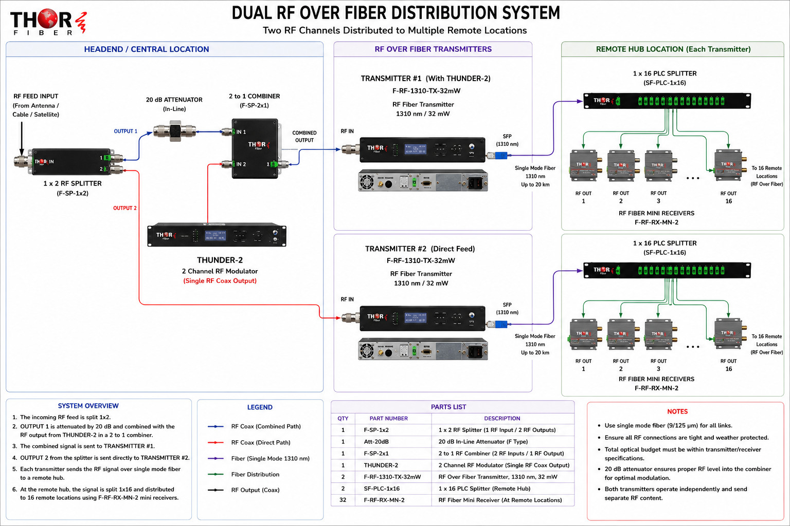
The original CATV feed and the THUNDER-2 output may not enter the combiner at equal RF levels. The inline attenuator reduces the level of the selected branch before combining so the existing carriers and locally generated carriers can be balanced more effectively.
The final attenuation value should always be confirmed with an RF meter or spectrum analyzer. The objective is not simply to reduce signal strength; it is to provide the optical transmitter with a properly balanced composite RF spectrum.
Converts two HDMI sources into two digital television channels and provides them through one combined RF coax output. The output can be inserted into an existing CATV system using an RF combiner.
A high-power 1310 nm optical transmitter designed to transport a complete CATV or broadcast RF spectrum over single-mode fiber. Its optical output is well suited to passive splitter networks and multi-building RF distribution.
Divides one optical RF signal into multiple passive fiber outputs. The 1×16 configuration provides distribution to as many as sixteen remote receiver locations while keeping the remote hub free of powered optical distribution equipment.
Converts the incoming optical CATV signal back into RF coax at each remote location. The recovered RF output can then feed the local coax network, an RF amplifier, or a building splitter system.
Distribute a shared television lineup while keeping administrative, educational or facility-specific channels local.
Carry the main campus CATV system to multiple buildings while adding local content at residence halls or athletic facilities.
Provide a common entertainment lineup while inserting property-specific channels at selected buildings.
Share the main RF lineup across a medical campus while adding local information or patient channels at specific wings.
Transport RF securely between buildings and limit location-specific programming to designated areas.
Distribute the main RF system throughout a venue while inserting local feeds in suites, press areas or control rooms.
No. Every receiver connected to the same optical transmitter and passive splitter receives the same RF spectrum. Different lineups require separate RF feeds, separate optical transmitters, or local insertion and filtering at selected branches.
That approach is possible, but custom traps may add cost, insertion loss and maintenance requirements. Keeping the private channels off the shared branch from the beginning is usually cleaner and easier to expand.
No. The THUNDER-2 creates two RF channels and places both channels on one combined coax RF output. That single output is connected to the RF combiner.
Yes, provided the transmitter power, splitter loss, fiber loss and receiver sensitivity remain within the calculated optical budget. Every link should be measured and verified before commissioning.
This system is designed for dedicated single-mode fiber. Confirm fiber type, connector type and optical loss before ordering or installing the equipment.
A shared CATV headend does not necessarily require every building to receive the exact same final channel lineup. By dividing the original RF feed into two branches, Thor Fiber can preserve the standard lineup for the remote facilities while adding private THUNDER-2 channels only to the location that requires them.
This architecture avoids expensive channel traps, keeps the optical network scalable, and uses standard RF and fiber components that are easy for technicians to understand and service. It is an effective design for campuses and multi-building systems where most programming is shared but selected facilities require local content.


 EN
EN