|
Technical Parameters
|
|
Light wavelength
|
1100 ~1600nm
|
|
Operating Wavelength
|
1550 nm ± 20nm ,built-in for filtering 1490 nm signal and remain 1550 nm signal to photo-diode
|
|
Optical input power range
|
0dBm to ~-15dBm (digital) & 0dBm to ~-10dBm (analog)
|
|
Frequency range
|
45MHz-1GHz
|
|
Output level
|
Output range: 65-75dBμV (Optical Input: -6 dBm)
Output range: 70-80dBμV (Optical Input: -2 dBm))
|
|
Flatness
|
±1dB
|
|
Slope
|
5dB ± 2dB
|
|
Return loss
|
16dB
|
|
Noise figure
|
47.5dB
|
|
CTB
|
≥65dB
|
|
CSO
|
≥65dB
|
|
MER
|
38
|
|
Power Consumption
|
≥ 0.6W
|
|
Test Conditions
|
60 CH (PAL-D), Pin -6dBm, 1 EDFA with noise figure 5dB, 25Km, Composite OMI 18.5%
|
|
Output impedance
|
75 Ω
|
|
Output port number
|
1
|
|
RF connector
|
F (female)
|
|
Responsibility
|
≥ 0.9 A/W @ 1550nm
|
|
Optical return loss
|
≥ 55 dB
|
|
LED indicator
|
Alarm LED:
Green on: receive power in range (about -6 to 0 dBm)
Red: low (<-8dBm) or lost signal
|
|
Power LED: Red = Power on
|
|
Power Adapter
|
Input Voltage: 90-250V AC@50-60Hz
|
|
Output Voltage uncertainty ≤ 3% without load
|
|
Output Voltage: Continous current ≥ 90% nominal current;
±5% nominal DC Voltage; Ripple Voltage (Vpp) ≤150mV
|
|
Voltage surge arrester equipments integrated.
|
|
Housing material
|
Stainless Metal with wall-mount Flange
|
|
Working environment
|
Operating temperature -20 + 55 °C
|
|
Size (W)*(D)*(H)
|
36*76.5*23mm
|
IMPORTANT NOTE*** (it is very important to interface our unit with SC/APC - Angle Polished Connector to avoid any light reflections.
If your fiber is terminated with the SC, ST, FC /PC flat connector, you need to use an optical jumper from PC type to SC/APC for proper conversion.
-----------------------------------------------------------------------------------------------------------------------------------------------------------------------
Quick Installation guide
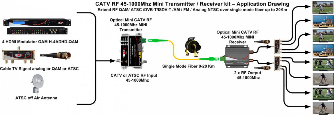
The Mini Transmitter and Mini Receiver set are plug and play devices if the RF input power to the TX and optical power Input to the RX are in the specified range.
TX RF INPUT 15-25dBmV (75-85dBuV) RX Optical INPUT should be +2 - 6dBm
TRANSMITTER:
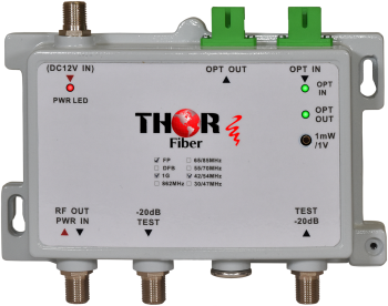
1) Connect Power Supply to the Transmitter
2) Connect CATV RF Input to the F port connector - Please note, the RF Power should be between 15-25dBmV (75-85dBuV)
3) Connect fiber optic cable to the Mini Transmitter Output - The Connector type MUST be SC/APC, never use SC/PC (Blue flat connector) NEVER LOOK DIRECTLY INTO THE UNITS OPTICAL OUTPUT (you could burn your eye)
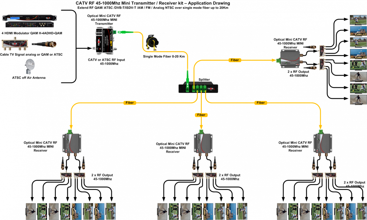
4 ) For short distance, point to point transmission, please plug 5db fiber optic attenuator, included in the box. (if the transmitter is used with a fiber optic splitter, the attenuator is not needed due to splitters insertion loss). The fiber loss is about 0.35db/km in 1310nm wavelength there is also some slight loss in path panel junctions typically 0.1 -0.5db per junction
5) The TX should show "ON" on the LCD, meaning it is transmitting and outputting an optical signal.
RECEIVER:
1) Connect POWER Supply to the Receiver, "No Light Input" or "Level too Low" the LED will be RED
2) Connect CATV RF cable to the F port connector - RF Output, the output will be about 22dBmV (82 dBuV)
3) Connect fiber optic cable to the Mini Receiver INPUT – The Connector type MUST be SC/APC, never use SC/PC (Blue flat connector) NEVER LOOK DIRECTLY TO THE FIBER JUMPER. (You will burn your eye)
4) The Optical level by the receiver should be about +2 to -6dBm
5) The LED should turn from RED to GREEN
5a) The RED LED means no Link Light detector
5b) The red light might also mean saturation, LEVEL TOO HIGH, it is easy to determine when you plug in the optical jumper the unit will go from RED to GREEN to RED again, it means the optical level is higher than +2Dbm , the receiver will still work correctly if this level will be not higher than +5dbm, If higher then +5, please add 5db attenuator included with your purchase.

 ES
ES


