Thor Broadcast Logo
Log in
Cart (0)
  • es ES
  • Products
    • CATV Modulators
      • HDMI RF Modulators
      • HD-SDI converters
      • IP to CATV Edge Modulators
    • DVB Encoders
      • IPTV Video Encoders
      • Hdmi RTSP RTMP RTSP Encoders
      • Transcoders, MPEG Converters, IP ASI Gateways
    • Decoders (IRD's & STB's)
      • RF input - Video /Audio Ouput
      • IP Broadcast Decoders
      • RF CATV and IPTV OTT STB's
    • Satellite Modulators
      • DVB-S/S2 Satellite Modulators
    • Fiber Optic Transport
      • SDI Fiber Optic Extenders, Digital Audio Extenders
      • SDI SD/HD/3G with CWDM
      • Cable TV CATV RF 45-900Mhz
      • L-Band Satellite RF 45-3000Mhz
      • Data & Ethernet over fiber
    • HDMI SDI Switchers, LAN Extenders, and Wireless Video Transport
      • HD Video Switchers and Signal Format Converters for AV Pros
      • Wireless HD SD Video Data Equipment
      • Video Audio Extenders Over Ethernet LAN IP Network
    • DIscounted Inventory
      • Satellite and CATV Broadcast Equipment for Sale
      • Lab Used Broadcast Equipment on sale
      • Past Generation Equipment
    • SDI Monitors
    • Warehouse
  • About
  • Client Portfolio
  • Support
      • Support Center Support Center
      • User Manuals User
        Manuals
      • Request an RMA Request an
        RMA
  • ⬇Download
    • Manuals
    • Datasheets
    • Quick Guides
  • Case Studies
    • THOR Gym
    • THOR Stadium
    • THOR Hotel
    • THOR University
  • Videos
  • Contact
  • Become a Reseller

Case Study: Local CATV Channel Insertion with RF over Fiber

Learn how Thor Fiber distributes a shared CATV lineup to multiple buildings while keeping private local channels at one facility using THUNDER-2 modulation, RF combining, a 32 mW optical transmitter, PLC splitters, and mini RF fiber receivers.

How to Keep Private CATV Channels at One Facility While Sharing the Main Channel Lineup

A practical multi-building RF-over-fiber design that avoids costly channel traps by splitting the original CATV feed, inserting local HDMI programming only on the required branch, and distributing both RF lineups over independent fiber paths.

CATV over Fiber QAM / ATSC Distribution Private Channel Insertion 32 mW Optical Transmitter 1×16 PLC Distribution

Table of Contents

  • The Customer’s CATV Distribution Challenge
  • Possible Ways to Solve the Problem
  • Recommended Thor Fiber Architecture
  • Thor Products Used in the Solution
  • Recommended Installation Sequence
  • Where This Design Can Be Used
  • Frequently Asked Questions
  • Conclusion

The Customer’s CATV Distribution Challenge

Existing System

The customer already had a centralized CATV headend producing a complete television lineup through one RF coax output. That lineup needed to be transported over existing single-mode fiber to multiple facilities and then converted back to coax at remote mechanical rooms.

The difficulty was that one facility also required two locally generated private channels. Those channels were intended only for that building and could not appear at the other locations.

Required Outcome

  • Keep the original CATV lineup available everywhere.
  • Add two private HDMI channels at one facility only.
  • Reuse the existing single-mode fiber infrastructure.
  • Avoid unnecessary filtering equipment.
  • Provide expansion capacity for additional remote nodes.
The key engineering question: How can one centralized RF feed support two different channel lineups without rebuilding the complete headend or installing expensive filtering at every destination?

Possible Ways to Solve the Problem

1

Channel Filters or Traps

Custom RF traps can be installed to suppress selected channels before the signal reaches specific buildings. This is a traditional approach, but it can become expensive and inflexible.

  • Requires filters designed for the exact RF channel plan.
  • May affect neighboring carriers if alignment is poor.
  • Future channel changes may require new filters.
  • Creates additional RF insertion loss.

Best for: fixed systems that will rarely change.

2

Separate Headends or Separate Feeds

Each facility can receive an independently assembled RF lineup through separate modulators, combiners and fiber transmitters.

  • Provides maximum control over every location.
  • Clean and technically straightforward.
  • Requires more headend equipment.
  • Higher cost when many lineups are needed.

Best for: sites requiring completely independent programming.

3
RECOMMENDED

Local Channel Insertion

Split the original RF feed into two branches. Send one branch directly to the remote facilities and combine the second branch with locally generated THUNDER-2 channels before sending it to the facility requiring private programming.

  • No custom channel traps required.
  • Private channels remain on one RF branch.
  • Easy to modify the local channel content.
  • Uses standard splitters, attenuators and combiners.

Best for: one shared lineup plus selected local channels.

What About “Jamming” or Frequency Overwrite?

In closed CATV systems, installers sometimes use the word jamming to describe intentionally placing a locally generated digital carrier on a selected RF channel so that the local content replaces or dominates the original program on that branch.

A more accurate engineering term is controlled channel replacement, frequency overwrite, or local carrier insertion. This is performed inside a closed coax network and should not be confused with transmitting radio-frequency interference over the air.

Important: Carrier overwrite requires careful level control. The locally generated RF carrier must be placed on the correct frequency and balanced against the existing RF spectrum. Poor level matching can reduce MER, create interference, or affect adjacent channels. Where possible, using an unused channel is cleaner than overwriting an active one.
Solution Initial Cost Flexibility RF Complexity Best Use
Channel Filters / Traps Medium to High Low Precision filtering required Permanent, fixed channel plans
Separate Headends High Very High More equipment and management Completely different lineups
Local Modulator + Combiner Moderate High RF level balancing required Shared lineup with local private channels

Recommended Thor Fiber Architecture

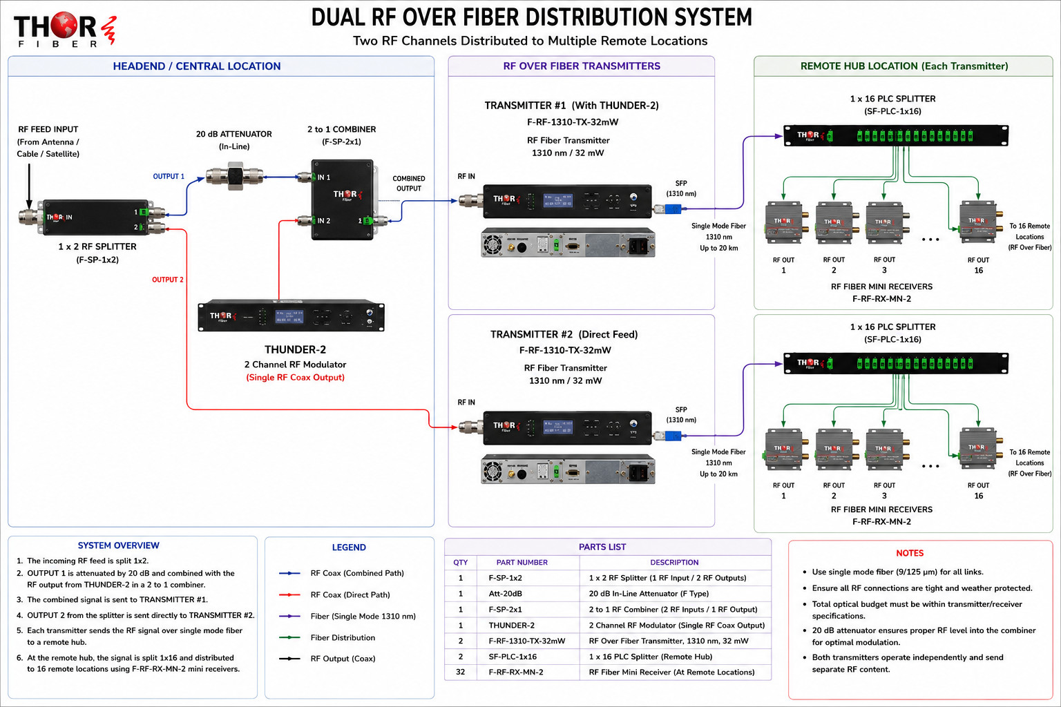
The selected design creates two independent RF-over-fiber paths from the same source feed. The original RF input first enters a 1×2 RF splitter with one F-type input and two F-type outputs.
Path A: Main CATV Lineup Plus Private Channels

  1. The first output of the 1×2 RF splitter passes through a 20 dB inline RF attenuator.
  2. The attenuated main RF feed connects to Input 1 of a 2-to-1 RF combiner.
  3. The THUNDER-2 generates two digital RF channels from two HDMI sources.
  4. The THUNDER-2 uses one combined RF coax output containing both programmed channels.
  5. The THUNDER-2 output connects to Input 2 of the RF combiner.
  6. The combined RF output feeds the first 32 mW RF-over-fiber transmitter.
  7. At the remote hub, a 1×16 PLC optical splitter distributes the optical RF signal to as many as 16 receiver locations.

Path B: Original CATV Lineup Only

  1. The second output of the original 1×2 RF splitter feeds the second RF-over-fiber transmitter directly.
  2. No THUNDER-2 channels are inserted into this branch.
  3. A second 1×16 PLC optical splitter distributes the original RF lineup to remote receivers.
Main RF Feed
→
1×2 RF Splitter
→
20 dB Attenuator
→
2×1 Combiner + THUNDER-2
32 mW RF Transmitter
→
Single-Mode Fiber
→
1×16 PLC Splitter
→
Mini RF Receivers
Application diagram: one RF branch receives locally inserted THUNDER-2 channels, while the second branch carries the original CATV lineup directly.jpg
2 Independent RF paths
32 mW Optical transmitter power
1×16 Passive optical distribution
32 Potential receiver endpoints

Why the 20 dB Inline Attenuator Is Important

The original CATV feed and the THUNDER-2 output may not enter the combiner at equal RF levels. The inline attenuator reduces the level of the selected branch before combining so the existing carriers and locally generated carriers can be balanced more effectively.

The final attenuation value should always be confirmed with an RF meter or spectrum analyzer. The objective is not simply to reduce signal strength; it is to provide the optical transmitter with a properly balanced composite RF spectrum.

Thor Products Used in the Solution

H-THUNDER-2

Two-Channel HDMI to RF Modulator

Converts two HDMI sources into two digital television channels and provides them through one combined RF coax output. The output can be inserted into an existing CATV system using an RF combiner.

  • Two HDMI program inputs
  • Two independently configured RF channels
  • Single combined coax RF output
  • Suitable for private or locally generated TV programming
View THUNDER-2
F-RF-1310-TX-32mW

32 mW CATV RF Over Fiber Transmitter

A high-power 1310 nm optical transmitter designed to transport a complete CATV or broadcast RF spectrum over single-mode fiber. Its optical output is well suited to passive splitter networks and multi-building RF distribution.

  • 45–1000 MHz RF transport
  • 32 mW optical output
  • 1310 nm high-linearity DFB laser
  • Supports analog RF, QAM and ATSC signals
View RF Transmitter
F-PLC / SF-PLC SERIES

Passive Fiber-Optic PLC Splitter

Divides one optical RF signal into multiple passive fiber outputs. The 1×16 configuration provides distribution to as many as sixteen remote receiver locations while keeping the remote hub free of powered optical distribution equipment.

  • Available in multiple split ratios
  • Passive operation
  • Ideal for campus and multi-building networks
  • Connector options available for system compatibility
View Optical Splitters
F-RF-RX-MN-2

Mini Fiber-to-Coax CATV Receiver

Converts the incoming optical CATV signal back into RF coax at each remote location. The recovered RF output can then feed the local coax network, an RF amplifier, or a building splitter system.

  • Compact wall-mount design
  • Single-mode optical input
  • Standard coax RF output
  • Suitable for QAM, ATSC and analog RF distribution
View Mini Receiver

Recommended Installation Sequence

  1. 1 Document the RF channel plan. Confirm every existing channel and identify unused frequencies for the two private channels.
  2. 2 Measure the main RF feed. Record total composite power, carrier levels and MER before modifying the distribution system.
  3. 3 Install the 1×2 RF splitter. Use a model with one 75-ohm F-type input and two 75-ohm F-type outputs.
  4. 4 Create the direct branch. Connect Splitter Output 2 directly to the second F-RF-1310-TX-32mW transmitter.
  5. 5 Create the local insertion branch. Connect Splitter Output 1 through the 20 dB inline attenuator to Input 1 of the 2×1 RF combiner.
  6. 6 Configure the THUNDER-2. Assign two unused RF channels, verify modulation parameters, and connect its single RF output to Input 2 of the combiner.
  7. 7 Verify the combined spectrum. Check carrier balance, adjacent-channel performance and total composite RF level before connecting the first optical transmitter.
  8. 8 Connect both optical transmitters. Use compatible single-mode fiber and the correct optical connector type.
  9. 9 Install the remote PLC splitters. Confirm splitter insertion loss and total optical budget for every endpoint.
  10. 10 Install and test each mini receiver. Measure optical input and RF output at every remote location before connecting the building coax network.
Optical design requirement: Calculate the complete optical budget before installation. Include PLC splitter loss, fiber attenuation, connector loss, splice loss and a reasonable engineering margin.

Where This Design Can Be Used

Correctional Facilities

Distribute a shared television lineup while keeping administrative, educational or facility-specific channels local.

University Campuses

Carry the main campus CATV system to multiple buildings while adding local content at residence halls or athletic facilities.

Hotels and Resorts

Provide a common entertainment lineup while inserting property-specific channels at selected buildings.

Hospitals

Share the main RF lineup across a medical campus while adding local information or patient channels at specific wings.

Military and Government Sites

Transport RF securely between buildings and limit location-specific programming to designated areas.

Sports and Event Venues

Distribute the main RF system throughout a venue while inserting local feeds in suites, press areas or control rooms.

Frequently Asked Questions

Can the same transmitter send different channel lineups to different buildings?

No. Every receiver connected to the same optical transmitter and passive splitter receives the same RF spectrum. Different lineups require separate RF feeds, separate optical transmitters, or local insertion and filtering at selected branches.

Why not place the private channels into the main RF feed and filter them later?

That approach is possible, but custom traps may add cost, insertion loss and maintenance requirements. Keeping the private channels off the shared branch from the beginning is usually cleaner and easier to expand.

Does the THUNDER-2 have two separate RF outputs?

No. The THUNDER-2 creates two RF channels and places both channels on one combined coax RF output. That single output is connected to the RF combiner.

Can the optical signal be divided to sixteen remote locations?

Yes, provided the transmitter power, splitter loss, fiber loss and receiver sensitivity remain within the calculated optical budget. Every link should be measured and verified before commissioning.

Can multimode fiber be used for this CATV RF transport system?

This system is designed for dedicated single-mode fiber. Confirm fiber type, connector type and optical loss before ordering or installing the equipment.

Conclusion

A shared CATV headend does not necessarily require every building to receive the exact same final channel lineup. By dividing the original RF feed into two branches, Thor Fiber can preserve the standard lineup for the remote facilities while adding private THUNDER-2 channels only to the location that requires them.

This architecture avoids expensive channel traps, keeps the optical network scalable, and uses standard RF and fiber components that are easy for technicians to understand and service. It is an effective design for campuses and multi-building systems where most programming is shared but selected facilities require local content.

Justin White
Justin White
Broadcast Engineer
Broadcast engineer specializing in turnkey CATV and fiber-transport solutions. Experienced in designing and deploying complete encoding/decoding workflows to move virtually any signal over IP, fiber, and RF. Focused on ultra-low-latency headend architectures and custom mux/demux builds, supporting demanding environments across telecom, sports, education, hospitality, studios, live events, and mission-critical institutions worldwide.
View author page
Contact us

Thor Broadcast Sales

Email: [email protected]
Phone: 1(800)521-THOR (8467) Ext 1
FAX: 1(800)521-6384

Customer Service/ Support

Phone: 1-800 521-THOR(8467) Ext 2
Email: [email protected]

Case Studies

- Converting Clear QAM HDTV Channels to Analog RF NTSC for Multi-Site Distribution
- Stadium IPTV - Replay System
- Hotel HDMI-to-QAM TV Distribution
- University IPTV Lecture Systems

  • CATV Modulators:
    • HDMI RF Modulators
    • HD-SDI converters
    • IP to CATV Edge Modulators
  • DVB Encoders:
    • IPTV Video Encoders
    • Hdmi RTSP RTMP RTSP Encoders
    • Transcoders, MPEG Converters, IP ASI Gateways
  • Decoders (IRD's & STB's):
    • RF input - Video /Audio Ouput
    • IP Broadcast Decoders
    • RF CATV and IPTV OTT STB's
  • Satellite Modulators:
    • DVB-S/S2 Satellite Modulators
  • Fiber Optic Transport:
    • SDI Fiber Optic Extenders, Digital Audio Extenders
    • SDI SD/HD/3G with CWDM
    • Cable TV CATV RF 45-900Mhz
    • L-Band Satellite RF 45-3000Mhz
    • Data & Ethernet over fiber
    • Analog Audio Video
    • Fiber Amplifiers - EDFA
    • DVB - ASI
    • Fiber Jumpers, Cables, Attenuators,
    • Optic Splitters Couplers CWDM Muxes
    • Optical Meters, Test Equipment, Accesories
    • Analog Baseband Video Audio, RS485/422/232 Data, Contact Closure
  • HDMI SDI Switchers, LAN Extenders, and Wireless Video Transport:
    • HD Video Switchers and Signal Format Converters for AV Pros
    • Wireless HD SD Video Data Equipment
    • Video Audio Extenders Over Ethernet LAN IP Network
  • HD 4K Cameras, SDI - HDMI - IP Streaming - PTZ - Broadcast and Security:
    • PTZ Streaming Cameras Broadcast cameras with SDI ,HDMI CVBS USB
  • DIscounted Inventory:
    • Satellite and CATV Broadcast Equipment for Sale
    • Lab Used Broadcast Equipment on sale
    • Past Generation Equipment
  • SDI Monitors:
  • Warehouse:
Thor Broadcast Logo
Email: [email protected]
Phone: 1(800) 521-8467 Ext 1
FAX: 1(800)521-6384
Information:
  • About us
  • Client Portfolio
  • Become a Reseller
  • Contact
  • Articles
  • Return Policy
  • Shipping Policy
  • International Order Policy
Popular:
  • RF Modulator
  • HDMI over COAX
  • HDMI over IP
  • COAX to HDMI
  • HDMI to SDI

Thor Broadcast
Torrance Business Park
2421 W 205th St
Torrance
CA 90501

© 2026 Thor Broadcast
Subscribe to our newsletter

Sign up here to get the latest news, updates and special offers delivered directly to your inbox.

You can unsubscribe at any time
newsletter image