| Availability: | In stock | Condition: | new |
|
| Shipping: | starting at $0.00 | Warranty: | 2Yrs |
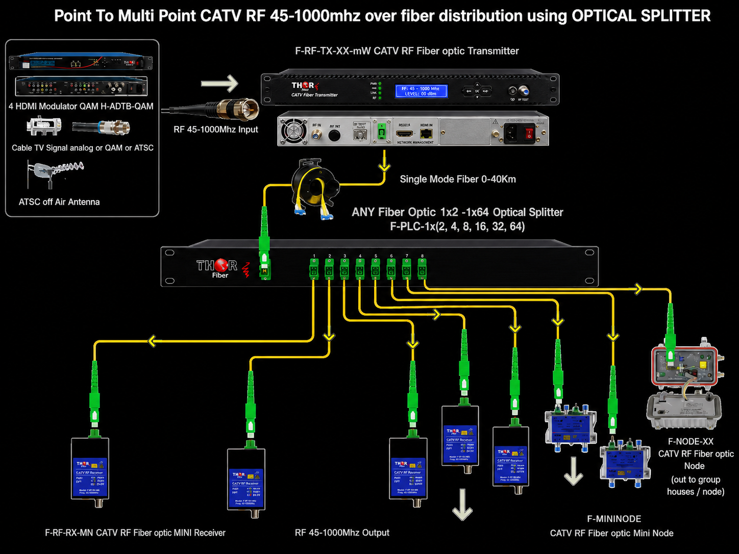
Long-distance CATV and broadcast RF distribution over fiber for large-scale networks and FTTH deployments.
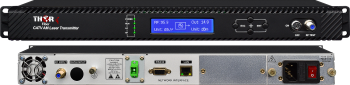
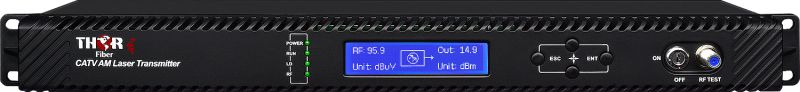
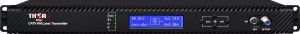
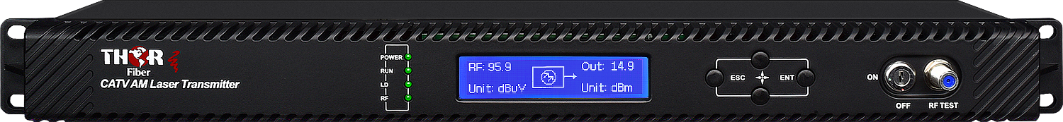
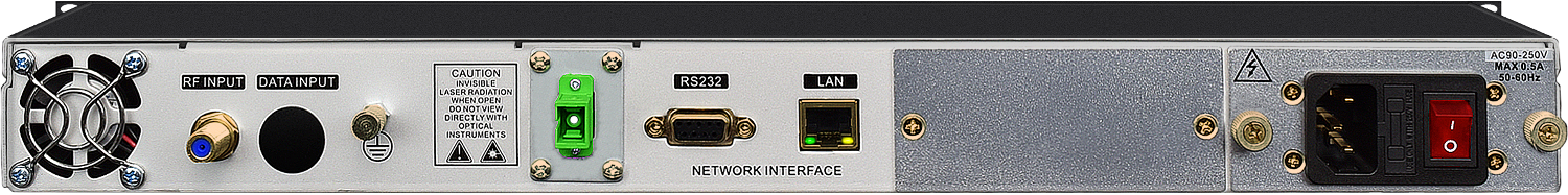
The F-RF-1310-TX-32mW is a high-output RF over Fiber transmitter designed for demanding applications requiring extended reach and large optical distribution networks. Covering the full 45-1000 MHz RF spectrum, it enables the transport of complete CATV lineups and RF services over fiber infrastructure.
This unit supports a wide range of modulation types, including Analog RF (NTSC / PAL), Digital QAM (J.83B), ATSC antenna feeds, ATSC 8VSB, ATSC 3.0, and other RF signals within the band. All services are carried simultaneously over a single optical link, preserving channel quality across long distances.
Built with a high-linearity DFB laser and advanced Automatic Gain Control (AGC), this transmitter is optimized for dense channel loading and high MER performance, making it ideal for modern digital RF environments.
With a powerful 32mW optical output, this transmitter is engineered for high split-ratio passive optical networks, supporting configurations such as:
This makes it an excellent solution for FTTH RF overlay systems, large hospitality properties, stadiums, military bases, and enterprise-wide CATV distribution over fiber.
The 32mW transmitter is designed for large and complex RF networks, including:
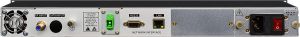
This transmitter integrates seamlessly with RF headend equipment such as QAM and ATSC modulators, antenna feeds, and CATV sources. It can be deployed with optical splitters and receivers to create scalable, low-loss RF distribution networks.
| Model | F-RF-1310-TX-32mW |
| Wavelength | 1310nm |
| Optical Power | 32mW |
| Frequency Range | 45-1000 MHz |
| Supported Signals | NTSC, PAL, QAM J.83B, ATSC, ATSC 3.0, 8VSB |
| Laser | High-Linearity DFB |
Enables large optical splits and extended reach, reducing the need for amplification and simplifying network design.
Browse related solutions: RF over Fiber Systems | CATV RF Solutions | RF Modulators
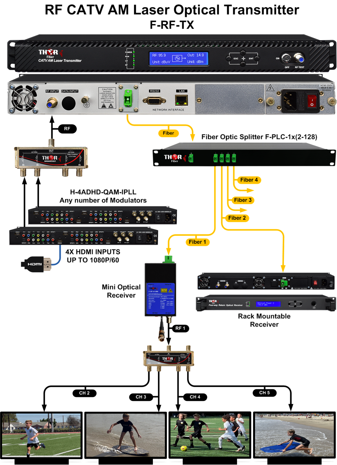
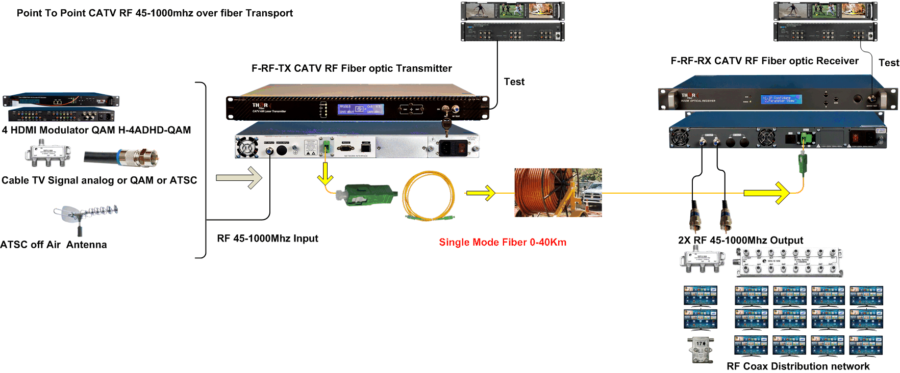
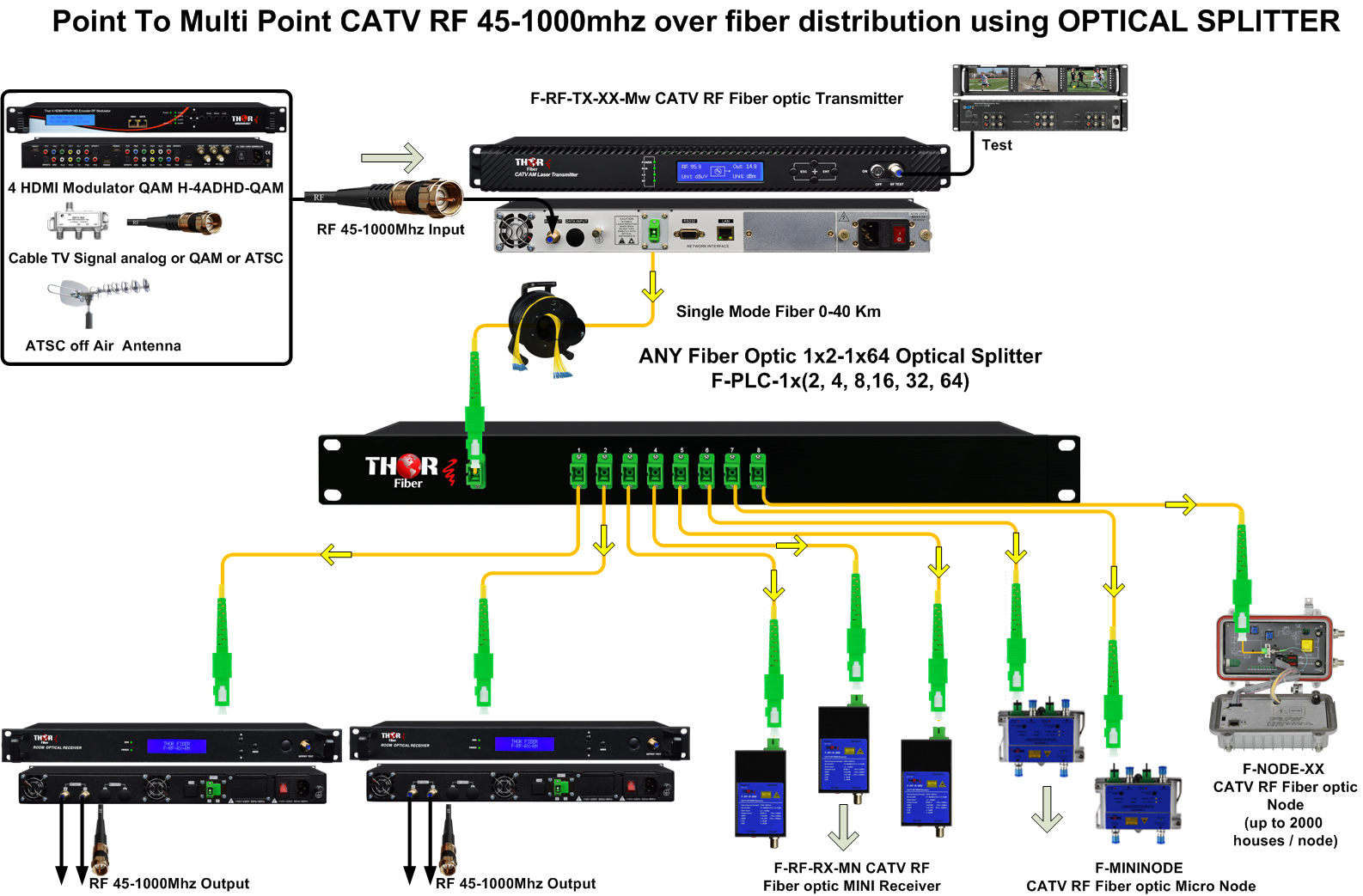
Example signal flow: HDMI sources enter a Thor modulator, the RF output feeds an RF optical transmitter, the fiber is split using PLC splitters, and multiple optical RF receivers convert the signal back to coax for TVs or local RF amplifiers.


Transmitter can be used with any Thor Fiber optical RF receiver.
- 32 mW Optical Power Output from sensor-feedback-controlled laser system
- Transports the entire 45-1000 MHz band even with full channel lineups
- Creates high-security "Fiber Breaks" to eliminate coax signal return path
- Automatic Gain Control (AGC) manages RF level with no adjustment needed
- Compatible with all Thor RFoG CATV series optical receiver systems
IMPORTANT NOTE*** (It is very important to interface our unit with an SC/APC - Angle Polished Connector to avoid any light reflections.)
If your fiber is terminated with the SC, ST, FC/PC flat connector, you need to use an optical jumper from PC type to SC/APC for proper conversion.
The following CATV RF fiber optic transmitters are available. You can view all models here: CATV RF over Fiber Transmitters
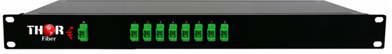
The Thor F-PLC passive fiber optic splitter with SC/APC connectors is an ideal accessory for CATV RF optical transmitters, allowing one optical signal to be split and routed to multiple locations over fiber. Available in 1x2 to 1x64 versions, it is perfect for RF over fiber distribution systems in hotels, campuses, apartment buildings, and other multi-location installations.
Learn more about Thor F-PLC Splitters →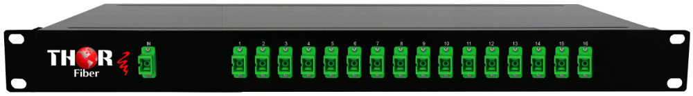
| *All Specifications Subject to Change Without Notice | |||
|
1x Type-F connector - 75 Ohm |
||
|
1310nm | ||
|
< 1 MHz FWHM | ||
|
>20 dB XP | ||
|
< -160 dB/Hz | ||
|
32 mW | ||
|
>55 dB | ||
|
SC/APC - Angle Polished IMPORTANT NOTE*** (It is very important to interface our unit with an SC/APC - Angle Polished Connector to avoid any light reflections.) If your fiber is terminated with the SC, ST, FC /PC flat connector, you need to use an optical jumper from PC type to SC/APC for proper conversion. |
||
|
11-29 dBmV AGC Managed | ||
|
<+/- 0.75 45 - 862 MHz | ||
|
>17 dBm | ||
|
>50 dB @ 10km fiber length | ||
|
< -63 dB | ||
|
< -57 dB | ||
|
19 x 10 x 1.75 inch | ||
|
2.5 kg | ||
|
0 - 45 ? | ||
F-RF-1310-TX-32mW transmitter
F-RF-RX-RM receiver
https://thorbroadcast.com/product/catv-rf-fiber-receiver-high-rf-power-rack-8230.html
F-PLC-1x16-SC/APC optical splitter
https://thorbroadcast.com/product/1-x-2-to-1-x-128-fiber-optic-couplers.html/227
Since the transmitters and receivers all use SC/APC, I would make sure the PLC coupler follows suit to minimize any reflections.
There are several types of losses that can occur in fiber optic cables, including:
Insertion loss: This is the loss of signal power that occurs when light is transmitted through the fiber. It is typically caused by imperfections in the fiber itself, such as bends, scratches, or impurities.
Splice loss: This occurs when two fibers are joined together, typically through a splicing process. Losses can occur due to imperfections in the splicing technique, as well as the difference in the refractive index between the fibers being spliced.
Connector loss: This occurs when light is transferred between two fibers through a connector. Losses can occur due to imperfections in the connector itself, such as dirt or damage.
Absorption loss: This is caused by impurities in the fiber that absorb light, reducing the signal strength. The main cause of absorption loss is the absorption of water molecules in the core of the fiber.
Scattering loss: This is caused by microscopic variations in the refractive index of the fiber, which cause light to scatter and be absorbed.
Macrobending Loss: This is caused by the fiber being bent in a radius of curvature that is too large. This causes the light to be reflected back into the cladding and is lost.
The use of passive optical splitters results in each splitter having its own insertion loss. For example, the F-FOS-1x2 1x2 splitter has a 4.5dB insertion loss
These losses can be mitigated by using high-quality fiber optic cables, connectors, and splicing techniques, as well as by regularly inspecting and maintaining the fiber optic network.
Insertion loss in fiber refers to the loss of signal power that occurs when light is transmitted through a fiber optic cable. In single mode fiber, insertion loss is typically measured at 1310nm and 1550nm wavelengths, which are the most commonly used wavelengths for long-distance telecommunications.
The insertion loss at 1310nm is typically higher - 0.35dB/km than at 1550nm -0.25dB/km, due to the fact that the attenuation coefficient at 1310nm is smaller than at 1550nm. However, the use of 1550nm allows for a larger transmission window and can support higher bandwidths, making it more suitable for high-speed data transmission.
Insertion loss can also occur at the connections and splices within a fiber optic cable. These losses are caused by imperfections in the connectors and splicing techniques, as well as by the difference in the refractive index between the fibers being spliced. To minimize these losses, high-quality connectors and splicing techniques must be used. This loss should not exceed 0.1dB per connection
. Additionally, insertion loss can occur at connections and splices due to imperfections in connectors and splicing techniques. To minimize these losses, high-quality connectors and splicing techniques must be used, This loss should not exceed 0.1dB per connection
--
To calculate the optical budget, you need to take into account all of the losses that occur in the fiber optic link, including attenuation, connector loss, and splice loss. The optical budget is calculated by subtracting the total losses from the transmitter output power.
In this case, the transmitter outputs +15dBmV and the receiver has 0dBmV receiver sensitivity. To calculate the optical budget, you would subtract the receiver sensitivity from the transmitter output power:
Optical budget = Transmitter output power - Receiver sensitivity Optical budget = +15dBmV - 0dBmV Optical budget = 15dB
It's important to note that the receiver sensitivity is usually given in negative dBmV. So, in this case, the receiver sensitivity of 0dBmV is equivalent to -0dBmV.
It's also important to note that the optical budget should be greater than the receiver sensitivity to ensure that there is enough power to reach the receiver and also to take into account any other losses that may occur in the link.
Additionally, depending on the application, the optical budget should be designed with a margin of safety, to account for changes in the link such as temperature, aging, or unexpected loss.
1)
Okay, we certainly have the gear available that you need, but to narrow it down, I just have a couple of basic questions. What is the distance of your single-mode fiber? Do you already have SC/APC terminations on the singlemode? Do you need bidirectional, or is this application going unidirectionally? If this is unidirectional transmission (Cable TV video only) you can use those TX/RX units. 1 single-mode fiber is required. SC/APC fiber connects F-RF-TX-MN-2mW https://thorbroadcast.com/product/thor-optical-mini-catv-rf-transmitter-45-1000mhz.html F-RF-RX-MN-2 https://thorbroadcast.com/product/thor-fiber-optical-mini-ftth-rf-catv-cable-tv-receiver-8230.html If this is bidirectional (Cable TV + Internet) You can use this unit. 2 single-mode fibers are required. SC/APC fiber connects F-RFoF-TX/RX https://thorbroadcast.com/product/coax-cable-bi-directional-catv-rf-transmitter-and-receiver-over-fiber-8230.html
2)
Unfortunately not, because it is impossible to put RF on multimode; no company offers such a product because it simply won't work. It's absolutely mandatory to use singlemode fiberGreat question — this is the core of how DOCSIS / CMTS systems actually work, and once you see it, it all clicks.
I’ll break it down step-by-step in a practical way (not textbook).
???? Big PictureYou’re thinking:
“If 500–1000 modems are all transmitting RF back on the same cable… why don’t they collide?”
???? Short answer: They DO NOT transmit at the same time.
The CMTS acts like a traffic controller and strictly schedules who is allowed to talk and when.
???? Downstream (Easy Part)From CMTS → Modems:
???? This is simple — like IPTV or RF broadcast.
???? Upstream (This is the Key Part)From Modems → CMTS:
???? This is NOT continuous QAM like downstream ???? It is time-controlled burst transmission
???? Think of It Like ThisImagine 1000 people sharing one microphone
Instead of everyone talking at once:
???? The CMTS says:
This is called:
???? TDMA (Time Division Multiple Access)
???? How Modems Stay SynchronizedThis is where DOCSIS is very smart:
1. Ranging (Distance Measurement)Each modem:
? So all signals arrive aligned at the CMTS
2. Power ControlCMTS adjusts modem power:
? So all signals arrive at similar levels
3. Timing SlotsThe upstream channel is divided into:
???? mini time slots (microseconds)
Each modem is assigned:
? No overlap → no collisions
???? What Modulation is Used Upstream?Not always the same as downstream.
Typical:
???? Lower modulation = more robust for noise
???? How 1000 Modems Share One ChannelExample:
Let’s say:
???? Not all are transmitting at once
Real behavior:
This is called:
???? Statistical multiplexing
???? Data Flow (Ethernet → RF)Inside each modem:
Step 1 – Ethernet InputUser traffic enters:
Modem:
CMTS sends:
???? “You can transmit now (time slot X)”
Step 4 – Burst TransmissionModem:
CMTS:
Because of 3 controls:
? 1. Time separationOnly one modem transmits per time slot
? 2. Power levelingAll signals arrive at similar strength
? 3. Timing alignmentAll bursts arrive perfectly aligned
???? Important Concept???? The upstream is NOT continuous RF ???? It is short bursts from many devices
This is why your RF over fiber system works:
? It just transports RF ? It doesn’t care what’s inside ? CMTS logic still controls everything
???? Real-World ExampleLet’s say:
CMTS schedules:
This happens thousands of times per second.
???? Why This Scales to 1000+ ModemsBecause:
???? It’s like a Wi-Fi network — but fully controlled and scheduled
Instead of random collisions (Wi-Fi):
???? CMTS enforces strict order
???? Key TakeawaysHere’s a clean logical diagram of your setup:
HEADEND ????????????????? ? CMTS ? ? (Down + Up RF)? ????????????????? ? RF (Coax) ? ???????????????????????? ? 1310nm TX (Forward) ? ???????????????????????? ? Fiber (SM, SC/APC) ? ????????????????????? ? Optical Splitter ? ? (1x8 / 1x32) ? ????????????????????? ? ? ? ??????????????? ? ??????????????? ? FIELD / DOCK AREAS (xN)
????????????????????????????????? ? Mini Node (Optical → RF) ? ? F-MININODE-2RP-HP ? ????????????????????????????????? ? RF (Coax) ? ?????????????????????????? ? Splitters / Cabling ? ?????????????????????????? ? ???????????????????????????? ? Cable Modems ? ? (Boats / Users) ? ????????????????????????????
================= RETURN PATH =================
Cable Modems (Upstream RF 5–45 MHz) ? ? RF ????????????????????????????????? ? Mini Node (RF → Optical) ? ????????????????????????????????? ? Fiber (DEDICATED) ?
HEADEND RETURN RECEIVERS
???????????????????????????????? ? 4ch Return RX (F-RF-RP4RX) ? ???????????????????????????????? ? RF Combined ? ????????? ? CMTS ? ?????????
???? 2. What’s REALLY Happening (Over Fiber)
Now let’s connect this with the DOCSIS behavior you asked about.
???? KEY IDEA???? Your fiber system is NOT doing any routing, switching, or packet handling
???? It is ONLY doing:
So:
? CMTS still controls everything ? Modems behave exactly the same as coax network
???? Forward Path (CMTS → Modems) Flow:???? This is identical to coax — just longer distance
???? Return Path (THIS IS THE IMPORTANT PART) Flow:Because your system preserves:
? TimingDOCSIS timing slots stay intact
? Power levelsNodes + CMTS control levels
? Burst structureNothing changes — still time-based bursts
???? IMPORTANT INSIGHT (This is GOLD for you)???? The fiber system behaves like:
“A very long, very clean coax cable”
???? No Collisions StillEven over fiber:
This is critical:
Forward:? Can split (broadcast)
Return:? Cannot combine optically
Why?
Because:
So instead:
???? Each node = dedicated return fiber
Then:
???? Combine in RF domain at headend (controlled)
???? Real Example (Your Harbor)Let’s say:
???? No collisions ???? No overlap ???? Fully controlled
???? Why This Is BETTER Than Coax In coax system:? No distance issue ? No RF noise buildup ? No amplifier cascade ? Much cleaner return path
???? VERY IMPORTANT (For your design thinking)The ONLY thing you must ensure:
1. Optical levelsNode input ≈ 0 dBm
2. RF output from node~45 dBmV → enough for local distribution
3. Return levelsBalanced so CMTS sees ~0 dBmV
???? Simple Way to Explain to CustomerYou can say:
“We are extending your CMTS over fiber — the system behaves exactly like coax, just without distance and noise limitations.”
???? Bonus Insight (Why This Is Perfect for You)Your application (harbor + boats):
? Fiber backbone already exists ? Coax needed at dock ? WiFi unreliable
???? This solution = BEST FIT
 At the minimum I would go with an 8mW power transmitter to go with the 1x8 splitter
https://thorbroadcast.com/product/8-mw-catv-rf-over-fiber-tx-45-870-mhz.html
Then you have your choice of receivers; they're all on this page: https://thorbroadcast.com/products/cable-tv-catv-rf-45-900mhz
I would say numbers 2 & 3 are the most popular receivers for optical RF.
#9 is the rackmount option.
You don't need any return path configuration for a system like this, it will all be unidirectional, so it's fairly simple.
You just need to figure out where the splitter will go, if it's at your station and you will home run every receiver, or if you want to place the splitter near station 3 or 4, and have runs going to each end point from there.
At the minimum I would go with an 8mW power transmitter to go with the 1x8 splitter
https://thorbroadcast.com/product/8-mw-catv-rf-over-fiber-tx-45-870-mhz.html
Then you have your choice of receivers; they're all on this page: https://thorbroadcast.com/products/cable-tv-catv-rf-45-900mhz
I would say numbers 2 & 3 are the most popular receivers for optical RF.
#9 is the rackmount option.
You don't need any return path configuration for a system like this, it will all be unidirectional, so it's fairly simple.
You just need to figure out where the splitter will go, if it's at your station and you will home run every receiver, or if you want to place the splitter near station 3 or 4, and have runs going to each end point from there.
 8 mW CATV RF Over Fiber Tx 45-870 MHz
8 mW Fiber Optic RF Transmitter for television carrier signals or any other RF in the 45-870 MHz band. Transmits full-band signals with a linear response.
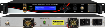 1550nm Externaly Modulated CATV RF Transmitter - Analog or QAM or ATSC CATV RF Over Fiber
1550nm DWDM Externally Modulated Optical Transmitter is an ideal solution for long-distance analog RF or digital QAM/ATSC from 45-1000Mhz over single-mode fiber. It has much better dispersion and stability than a 1550nm internally modulated fiber optic transmitter. If your fiber distance exceeds 30km, this is the perfect product for your application.
 ES
ES


