Learn how to properly select a CATV RF over fiber transmitter, optical splitter, and mini node receiver for reliable QAM and analog RF distribution over single-mode fiber.
Learn how to properly select a CATV RF over fiber transmitter, optical splitter, and mini node receiver for reliable QAM and analog RF distribution over single-mode fiber. This guide explains splitter insertion loss, optical budget, mini node input targets, RF attenuation, and how to design for long-term expansion.
Table of Contents
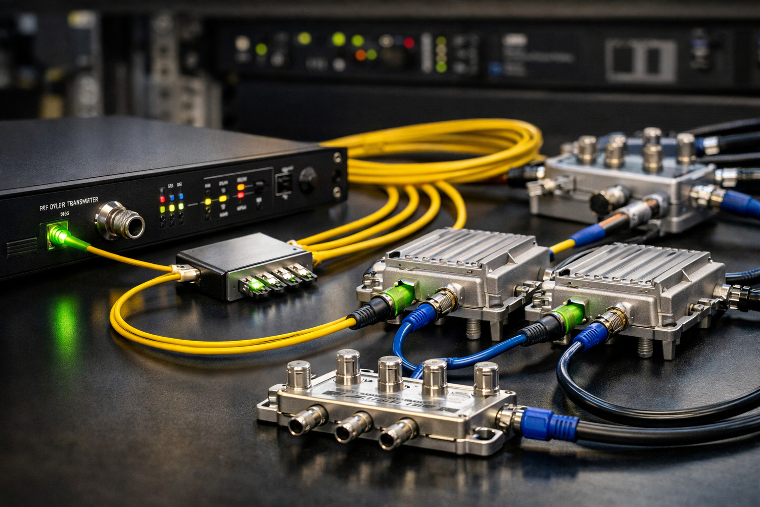
A properly designed RF over fiber system can distribute CATV, QAM, and broadband RF signals over long distances using single-mode fiber while maintaining excellent signal quality. The most important parts of the design are:
This article is based on a real-world customer consultation where the goal was to deliver RF over single-mode fiber with a return path while keeping the system scalable for future expansion.
4 mW RF Over Fiber Transmitter
Best for smaller systems using a 1x4 splitter and shorter total optical loss budgets.
8 mW RF Over Fiber Transmitter
Recommended for 1x8 splitters, longer runs, future expansion, and improved optical margin.
Mini Node with Return Path
High-performance CATV optical receiver with return path support for forward and reverse RF transport.
1x4 Optical Splitter
PLC splitter with approximately 7 dB insertion loss, suitable for four-way distribution.
1x8 Optical Splitter
PLC splitter with approximately 11 dB insertion loss, ideal for long-term scalability and future expansion.
The first major design question is whether to use a 4 mW transmitter or an 8 mW transmitter.
A 4 mW CATV RF over fiber transmitter is a good choice when:
An 8 mW CATV RF over fiber transmitter is recommended when:
Optical splitters divide one optical signal into multiple outputs. This is convenient for multi-node distribution, but every split introduces insertion loss.
| Splitter Type | Typical Insertion Loss | Use Case |
|---|---|---|
| 1x4 Optical Splitter | ~7 dB | Smaller systems with four optical outputs |
| 1x8 Optical Splitter | ~11 dB | Larger systems or installations planned for expansion |
Beyond splitter loss, your total optical budget also includes:
Even if the fiber distance is not extremely long, a system with a 1x8 splitter and several connectors can quickly consume the available optical budget. That is why the 8 mW transmitter is often the safer and more scalable choice.
The F-MININODE-2RP-HP mini node performs best when the received optical level is close to 0 dBm.
This matters because the optical input level directly affects the RF output quality of the node. When the node receives the proper optical level:
One of the most overlooked parts of an RF over fiber system is what happens after the mini node.
Mini nodes typically deliver a strong RF output. That is good because it allows downstream distribution, but it also means the signal often needs to be attenuated before feeding tuners, televisions, amplifiers, or additional RF splitters.
RF attenuation is the deliberate reduction of signal level so the downstream equipment receives a signal within its proper operating range.
If the RF level is too high:
In digital RF systems, more signal is not always better. A signal that is too hot can be just as problematic as one that is too weak.
That depends on:
| RF Splitter | Typical RF Loss |
|---|---|
| 2-way RF splitter | ~3.5 dB |
| 4-way RF splitter | ~7 dB |
| 8-way RF splitter | ~11 dB |
For example, if the mini node output is strong and then feeds only one or two devices, you may need significant RF attenuation pads. But if the node feeds a long coax run and then several downstream RF splits, less external attenuation may be needed because those components already reduce the level.
A customer needed to feed several remote endpoints over single-mode fiber. The installation used:
Since the project included multiple branches and possible future expansion, the recommended design was:
This approach gave the installer better optical margin, future expansion capability, and a better chance of keeping the mini nodes near the desired optical input level.
Q: When should I use a 4 mW transmitter?
Use a 4 mW transmitter when the system is relatively small, typically with a 1x4 splitter, moderate fiber distances, and minimal total optical loss.
Q: When should I use an 8 mW transmitter?
Use an 8 mW transmitter when you are using a 1x8 splitter, planning future expansion, or want additional optical margin to keep the mini nodes close to 0 dBm input.
Q: Why is the 1x8 splitter harder on the optical budget?
Because it introduces about 11 dB of insertion loss, compared to about 7 dB for a 1x4 splitter. That extra loss can make a major difference at the node input.
Q: Why should the mini node get close to 0 dBm optical input?
Because that is typically the sweet spot for stable and strong RF output with good digital performance.
Q: Why do I need RF attenuation after the mini node?
Mini nodes often output very high RF levels. Without attenuation, the downstream equipment may be overdriven, causing digital channels to fail or degrade.
Q: How do I know how much RF attenuation I need?
It depends on the node output level, the number of RF splits after the node, coax length, and the acceptable level at the receiving equipment. The correct approach is to calculate the full downstream RF path.

 EN
EN

