| Availability: | In stock | Condition: | new |
|
| Shipping: | starting at $0.00 | Warranty: | 1Yrs |
IMPORTANT NOTE*** (It is very important to interface our unit with SC/APC - Angle Polished Connector to avoid any light reflections.)
If your fiber is terminated with the SC, ST, FC/PC flat connector, you need to use an optical jumper from PC type to SC/APC for proper conversion.

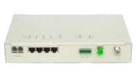
H-NMS - 10/100 Ethernet IP NMS GUI interface for remote monitoring over IP network OPTION FOR F-MININODE-2RP-HP
|
Item |
Unit |
Technical Parameters |
||
|
Optical Parameters |
||||
|
Receiving Optical Power |
dBm |
-9 ~ +2 |
||
|
Optical Return Loss |
dB |
>45 |
||
|
Optical Receiving Wavelength |
nm |
1100 ~ 1600 |
||
|
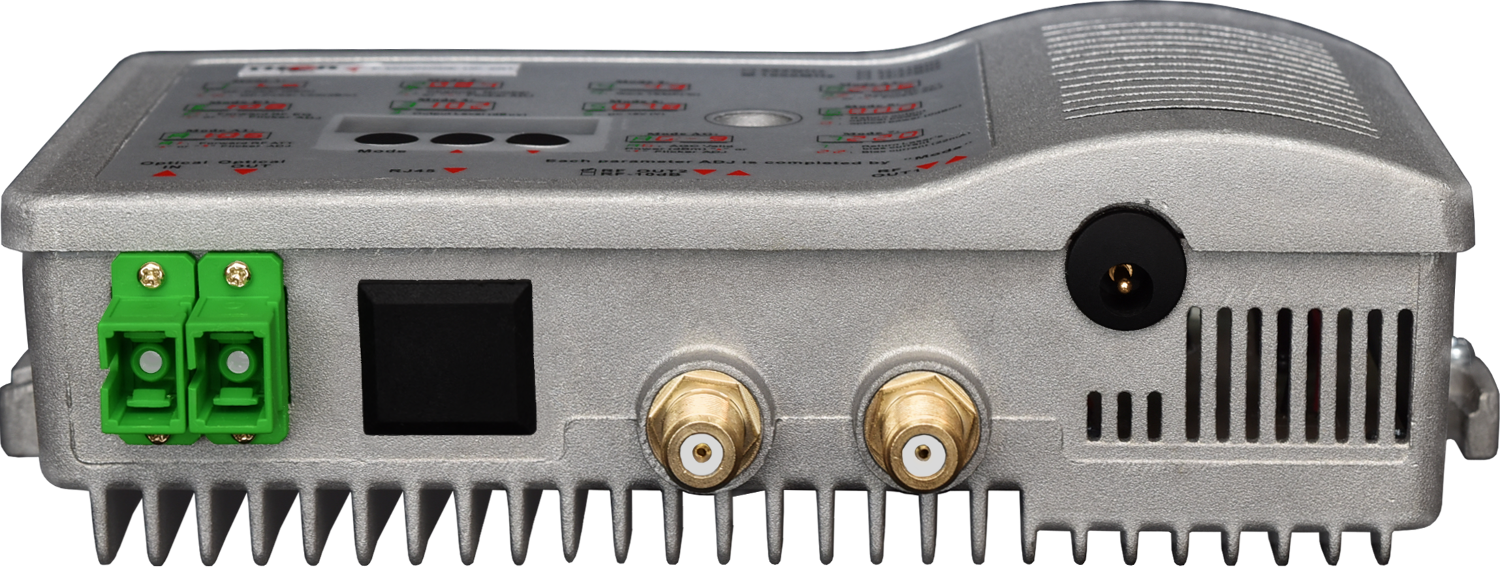
Optical Connector Type |
|
SC/APC IMPORTANT NOTE*** (It is very important to interface our unit with SC/APC - Angle Polished Connector to avoid any light reflections. If your fiber is terminated with the SC, ST, FC /PC flat connector, you need to use an optical jumper from PC type to SC/APC for proper conversion. |
||
|
Fiber Type |
|
Single mode |
||
|
Link Parameters |
||||
|
C/N |
dB |
>=51 |
Note 1 |
|
|
C/CTB |
dB |
>=60 |
||
|
C/CSO |
dB |
>=60 |
||
|
RF Parameters |
||||
|
Frequency Range |
MHz |
45 ~860/1003 |
||
|
Flatness in Band |
dB |
+/-0.75 |
||
|
|
( F-MININODE-2RP-HP-B one output) |
( F-MININODE-2RP-HP two output) |
||
|
Rated Output Level |
dBuV |
>= 108 |
>= 104 |
|
|
Max Output Level |
dBpV |
>= 108 (-9 ~ +2dBm Optical power receiving) |
>= 104 (-9 ~ +2dBm Optical power receiving) |
|
|
>= 112(-7~+2dBm Optical power receiving) |
>= 108 (-7 ~ +2dBm Optical power receiving) |
|||
|
Output Return Loss |
dB |
>=16 |
||
|
Output Impedance |
Ohm |
75 |
||
|
Optical AGC Range |
dBm |
(-9dBm / -8dBm / -7dBm / -6dBm / -5dBm / -4dBm) - (+2dBm) adjustable |
||
|
Electrical Control EQ Range |
dB |
0~15 |
||
|
Electrical Control ATT Range |
dB |
0~15 |
||
|
General Characteristics |
||||
|
Power Voltage |
V |
A: AC (150~265)V |
D: DC 12V/1A External power supply |
|
|
Operating Temperature |
deg C |
-40~60 |
||
|
Consumption |
VA |
<= 8 |
||
|
Size / Weight |
|
WEIGHT: 1.8 lb BOX SIZE (IN): 8 x 6.75 x 2.5 in BOX SIZE (MM): 204 x 172 x 64 mm UNIT SIZE (IN): 7.5 x 4.5 x 2.25 in UNIT SIZE (MM): 191 x 115 x 58 mm |
||


Adam: Just to clarify - the distances you're referring to are RF distances on coaxial cable, not the optical fiber portion of the system, correct?
Customer: Yes, that's correct. I'm referring to the RF side on the coax.
Adam: Okay. What equipment are you connecting to the output of the mini node? Are you going directly into TVs, or are there splitters or taps in between?
Customer: We're using multitaps. The taps feed the TVs directly.
Adam: Understood. And what value taps are you using?
Customer: We're using 26 dB taps.
Adam: That explains it. Our mini nodes output around +45 dBmV RF level.
If you use a 26 dB tap, the drop port already introduces about 26 dB of loss, which means the signal level going to the TV will be roughly:
+45 dBmV - 26 dB = about +19 dBmV
That level is actually perfectly acceptable for a TV.
Most TVs can reliably receive signals in the range of roughly +5 dBmV to +30 dBmV.
Customer: I see. In my calculations I started with the +45 output, then subtracted the 26 dB tap, and depending on the cable distance I thought I needed additional attenuation.
I may have been using too strict a target range. I was trying to keep the signal around 0 to +10 dBmV at the TV.
Adam: Yes, that range is a bit too strict. TVs can handle a much wider signal range than that.
We test these systems regularly, and even signals up to +30 dBmV typically work without issues.
Since the 26 dB tap already provides the necessary attenuation, you usually won't need additional attenuators unless you are feeding the TV directly without a tap.
Customer: That makes sense. So I was just being too conservative with my target signal level at the TV.
Adam: Exactly. Because the tap already introduces sufficient loss, you can typically use the system exactly as designed without adding extra attenuators.
Customer: Great. That answers my question. Thank you.
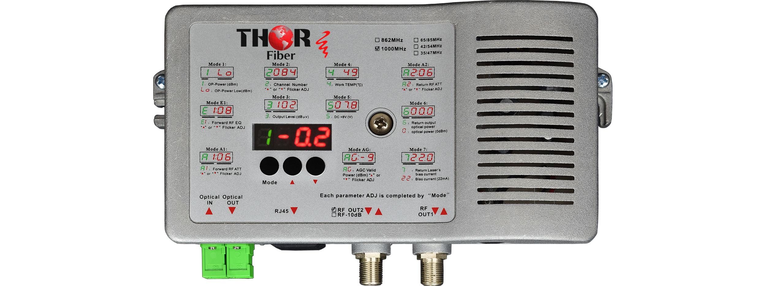
Access the node display
Look for optical input (example: 0.8 dBm)
Acceptable range:
Typically -8 dBm to +2 dBm
If within range, proceed.If too high, consider optical attenuation.
2. Verify RF Output LevelFiber nodes typically output very high RF levels
Measure using:
RF meter
Spectrum analyzer
Expect:
~+42 to +45 dBmV
Use RF pads (attenuators)
Example:
30-40 dB attenuation may be required
Goal:
Bring the signal down to ~0-15 dBmV at the tuner
Most nodes include built-in RF attenuation:
Navigate to: A1 (Forward Path Attenuator)
Set value:
Up to 15 dB
Important:
You may need to press and hold the buttons to activate adjustment mode
Best practice:
Use internal attenuation first
Fine-tune with external pads
Example:
15 dB internal
20-30 dB external
After adjustment:
Check if channels lock properly
Verify with:
RF analyzer (MER / BER)
TV or STB
If locking, the issue is resolved.If not, continue balancing.
Key InsightToo much RF power causes failure - not too little
QAM signals are digital:
They either lock cleanly or fail completely
Overdriving causes:
Distortion
Poor MER
No lock
You may see a setting like:
E1 - Forward Path Equalizer
Balances signal levels across frequencies
Compensates for cable losses (higher frequency loss)
Long coax runs
Uneven channel levels
Think of it as:
"Leveling" all channels evenly
If only using forward path:
Return laser is:
Inactive by default
Activates only when RF input is present (burst mode)
Keep unused optical ports covered
Prevent dust contamination
Check optical input powerMeasure RF outputAdd attenuation (external)Enable internal attenuation (A1)Re-test QAM lockFine-tune levels
Real-World Case InsightIn a recent installation:
Node output was too hot
Even with 35 dB external attenuation, QAM failed
Adding 15 dB internal attenuation: Immediately restored channel lock
The most common cause of QAM lock failure in fiber node installations is excessive RF signal level.
Proper attenuation and balancing are critical.
If your system shows:
No lock
Intermittent lock
Unstable channels
Always check RF levels first.
Need Help?Thor Broadcast engineers can assist with:
System design
RF balancing
Remote configuration
Call us anytime www.thorbroadcast.com
Mark: We’ll have a 4-way split, with:
3 active fiber runs
1 spare for future use
Distances:
Longest run: ~2,250 ft (with 2 splices)
Other runs: ~750 ft
Mark: Yes, there will be a return path.
Return frequency: ~21 MHz
Forward starts around 50 MHz
Adam: Perfect—that’s a standard forward + return CATV system.
Transmitter Selection Q: What transmitter should be used?Adam: You have two options depending on future expansion:
Option 1 – Current Need (4-Way Split)Use a 4 mW transmitter: ???? https://thorbroadcast.com/product/4-mw-catv-rf-over-fiber-tx-45-870-mhz.html
Ideal for:
1×4 splitter
Short to medium fiber runs
Most cost-effective solution
Use an 8 mW transmitter: ???? https://thorbroadcast.com/product/8-mw-catv-rf-over-fiber-tx-45-870-mhz.html
Supports:
1×8 splitter expansion
Longer distances / higher losses
Provides additional optical power margin
Adam’s Recommendation: ???? If future expansion is possible, go with the 8 mW transmitter
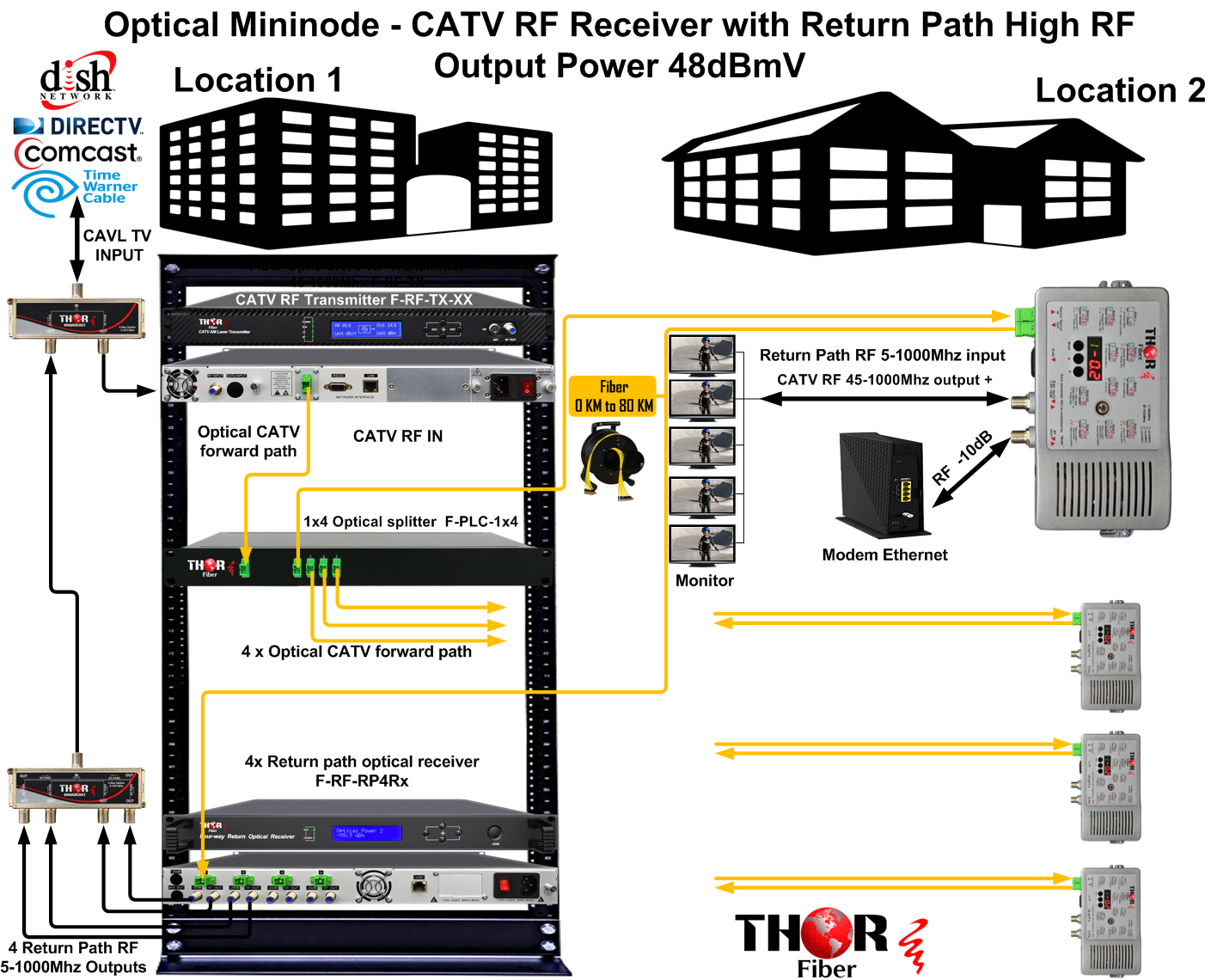
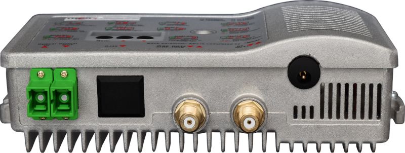
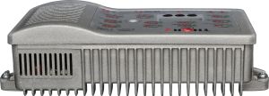
Receiver (Node) Selection Q: What node should be used on the receiving side?Adam: Use the Mini Node with Return Path: ???? https://thorbroadcast.com/product/optical-mini-node-catv-rf-receiver-with-return-path-8230.html
(Model: F-MININODE-2RP-HP)
Supports forward + return RF
High RF output level
Designed for CATV distribution
???? You will need:
1 node per fiber leg (4 total)
Use PLC Optical Splitters:
1×4 Splitter (Current System)???? https://thorbroadcast.com/product/1-x-2-to-1-x-128-fiber-optic-couplers.html/225
Designed for 4 outputs
Lower insertion loss
???? https://thorbroadcast.com/product/1-x-2-to-1-x-128-fiber-optic-couplers.html/226
Allows system expansion
Slightly higher insertion loss
Ideal for long-term scalability
Adam: Yes:
Splitters include protective caps
Always keep unused ports covered to:
Prevent dust contamination
Maintain optical performance
Adam: Use:
SC/APC connectors (green)
If different connectors exist:
Use conversion jumpers (LC, ST → SC/APC)
Adam: For your project, I recommend:
8 mW transmitter (future-proof)
1×8 PLC splitter
4 × Mini Nodes (F-MININODE-2RP-HP)
Return path receiver (if required at headend)
???? This provides:
Reliable performance
Expansion capability
Proper optical power margin
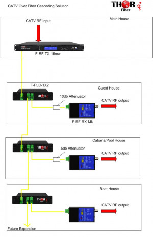
Summary
This system design includes:
? RF over single-mode fiber ? Forward + return path operation ? 4–8 way optical distribution ? High-performance CATV mini nodes ? Scalable architecture for future expansion
Need Help?Thor Broadcast can assist with:
System design
Product selection
RF level balancing
???? Contact our engineering team anytime
Adam: What you are describing is a typical forward RF path, generally in the 45 to 1000 MHz range, along with a return path in the 5 to 45 MHz range. Is that correct?
John: Exactly.
Adam: Okay. The design depends on how many nodes you plan to use. We offer transmitters from 4 mW up to 32 mW. If you choose a stronger unit, such as 16 mW or 32 mW, you'll have enough optical power to split the signal more easily - potentially to 16 or even 32 outputs, depending on the loss budget.
For example, if you only need 8 nodes, an 8 mW transmitter may be enough. If you want a more universal solution for multiple sites, a 32 mW transmitter would likely cover all cases.
John: Wouldn't a 32 mW transmitter overdrive the fiber node in the field?
Adam: No. The reason for using a stronger transmitter is to overcome the insertion loss of optical splitters. The receiver sensitivity at the node is typically around +3 dBm to -9 dBm, but the closer you are to 0 dBm, the more optimal the performance. It's always easier to attenuate optical power than to amplify it later.
John: Do you also carry fiber optic splitters?
Adam: Yes, absolutely. We have rack-mount splitters and LGX modules.
John: So just to confirm: CMTS -> transmitter -> fiber splitter -> multiple nodes?
Adam: Correct. The unit at the headend is the transmitter.
John: And at the node, it converts back to RF?
Adam: Exactly. The recommended node provides about +45 dBmV RF output.
John: Is it outdoor-rated?
Adam: We have outdoor options, but typically it's installed in a NEMA 4 enclosure. No ventilation is required.
John: Now about the return path - how do modems communicate back?
Adam: The node is bidirectional. The return path (5-45 MHz) is sent back over a second fiber. So each node uses:
At the headend, you use return path receivers (e.g., 4-channel units), then combine them and feed them into the CMTS.
John: And no throughput bottlenecks?
Adam: No - the node acts like a media converter (RF fiber). It does not limit throughput. The CMTS manages all bandwidth and scheduling.
John: Good - because we may have 500+ modems, maybe ~100 per node.
Adam: That's fine - same as coax architecture. Just confirm your return band is truly 5-45 MHz.
John: I believe so - about 8 upstream / 8 downstream channels.
Adam: That will work.
John: Can you send me links and a quote? This is for boat harbors - about 1,000 boats, each dock serving 40-50 users.
I need to calculate:
Adam: Understood. Typical losses:
You may place nodes per dock or per group of docks depending on the layout.
John: Exactly - it depends where fiber is available.
Adam: I recommend building a test section first.
We also have an RF-over-fiber specialist we can involve if needed.
John: Good idea. This could scale to 8-9 harbors, so it needs to be solid.
Are these used by cable operators?
Adam: Yes - these are carrier-grade solutions used by commercial operators.
John: And you're the manufacturer?
Adam: Yes - fully controlled design and production. Also NDAA compliant.
Adam: Where is your RF coming from?
John: Currently mostly empty spectrum - just CMTS channels. We may add off-air channels later.
Adam: We also offer QAM / ATSC modulators if you decide to inject channels.
John: We'll evaluate that later. Right now, the priority is avoiding line extenders.
Adam: Makes sense - the return path gets complicated with amplifiers. Fiber simplifies that significantly.
John: Exactly. That's why we're moving to fiber.
Adam: Right - fewer amplifiers, longer distances, easier balancing.
John: Perfect. Please send:
I'll review and get back to you this week.
Adam: Will do. I have your email - I'll send everything shortly.
John: If this checks out, we'll be ordering within a few weeks.
Adam: Great - once you finalize node count and layout, we'll size:
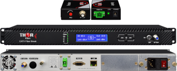 RF Fiber Break - optical RF COAX isolation solution
Low-cost RF Fiber Break system for high-security RF feeds. For short-distance transport over fiber and for RF security to prevent any RF leaks. Prevents coax from being used to transmit data in the return direction; using a Fiber Break Kit eliminates any possibility of your copper transmission returning on RF. Kit includes transmitter, fiber jumper, and mini-receiver.
 ES
ES


