| Disponibilidad: | En stock | Condición: | nuevo |
|
| Envío: | starting at $0.00 | Garantía: | 1Yrs |
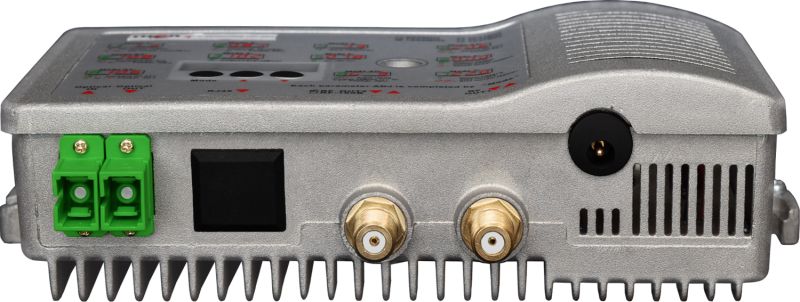
NOTA IMPORTANTE*** (Es muy importante conectar nuestra unidad con SC/APC - Conector Pulido en Ángulo para evitar cualquier reflexión de luz.)
Si su fibra está terminada con conector plano SC, ST, FC/PC, debe usar un jumper óptico de tipo PC a SC/APC para una conversión adecuada.
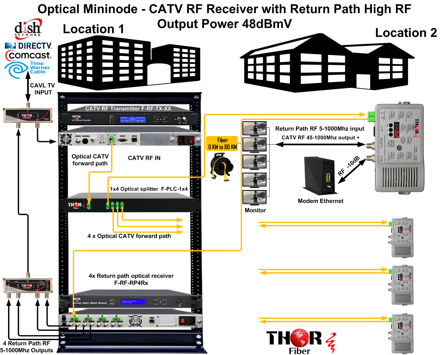

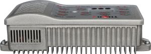
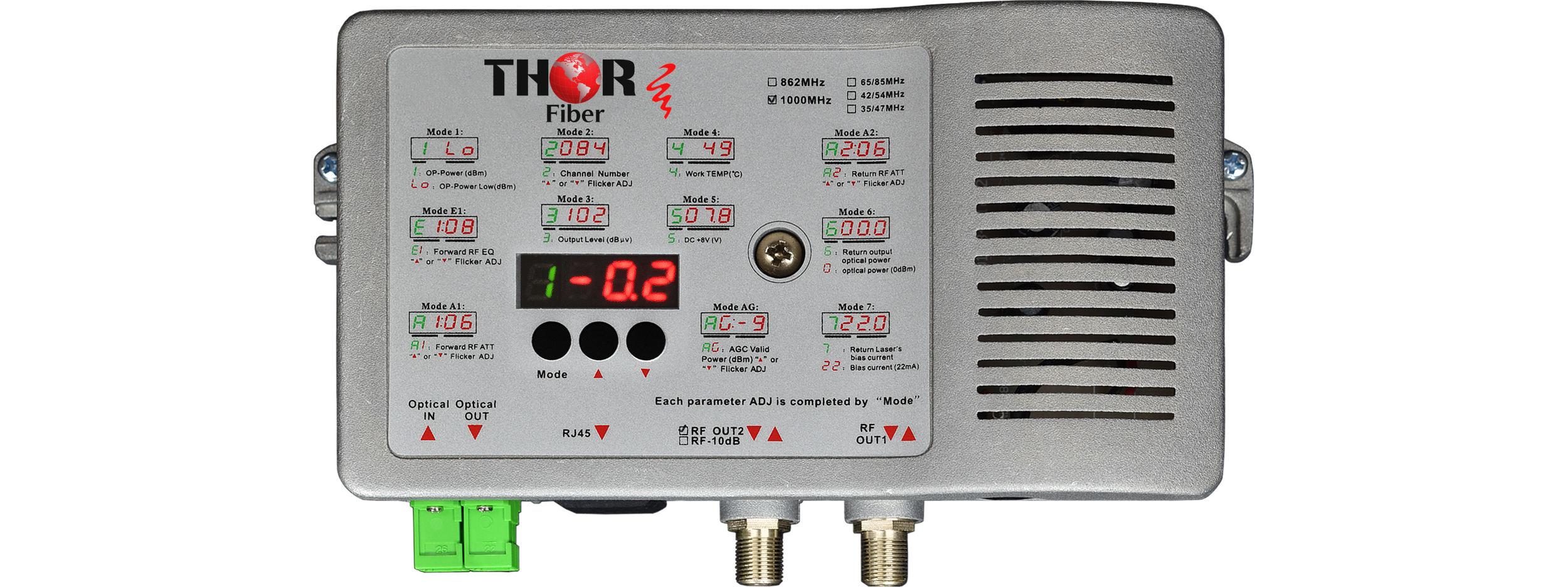
H-NMS - Interfaz GUI NMS IP Ethernet 10/100 para monitoreo remoto sobre red IP OPCIÓN PARA F-MININODE-2RP-HP
|
Ítem |
Unidad |
Parámetros Técnicos |
||
|
Parámetros Ópticos |
||||
|
Potencia Óptica de Recepción |
dBm |
-9 ~ +2 |
||
|
Pérdida de Retorno Óptico |
dB |
>45 |
||
|
Longitud de Onda Óptica de Recepción |
nm |
1100 ~ 1600 |
||
|
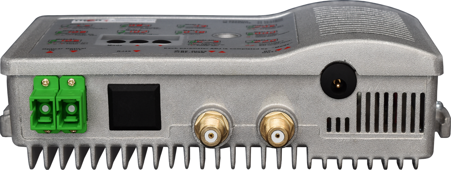
Tipo de Conector Óptico |
|
SC/APC NOTA IMPORTANTE*** (Es muy importante conectar nuestra unidad con SC/APC - Conector Pulido en Ángulo para evitar cualquier reflexión de luz.) Si su fibra está terminada con conector plano SC, ST, FC/PC, debe usar un jumper óptico de tipo PC a SC/APC para una conversión adecuada. |
||
|
Tipo de Fibra |
|
Monomodo |
||
|
Parámetros de Enlace |
||||
|
C/N |
dB |
>=51 |
Nota 1 |
|
|
C/CTB |
dB |
>=60 |
||
|
C/CSO |
dB |
>=60 |
||
|
Parámetros RF |
||||
|
Rango de Frecuencia |
MHz |
45 ~860/1003 |
||
|
Planitud en Banda |
dB |
+/-0.75 |
||
|
|
( F-MININODE-2RP-HP-B una salida) |
( F-MININODE-2RP-HP dos salidas) |
||
|
Nivel de Salida Nominal |
dBuV |
>= 108 |
>= 104 |
|
|
Nivel Máximo de Salida |
dBpV |
>= 108 (-9 ~ +2dBm potencia óptica de recepción) |
>= 104 (-9 ~ +2dBm potencia óptica de recepción) |
|
|
>= 112 (-7 ~ +2dBm potencia óptica de recepción) |
>= 108 (-7 ~ +2dBm potencia óptica de recepción) |
|||
|
Pérdida de Retorno de Salida |
dB |
>=16 |
||
|
Impedancia de Salida |
Ohm |
75 |
||
|
Rango AGC Óptico |
dBm |
(-9dBm / -8dBm / -7dBm / -6dBm / -5dBm / -4dBm) - (+2dBm) ajustable |
||
|
Rango de EQ Control Eléctrico |
dB |
0~15 |
||
|
Rango de ATT Control Eléctrico |
dB |
0~15 |
||
|
Características Generales |
||||
|
Voltaje de Alimentación |
V |
A: CA (150~265)V |
D: CC 12V/1A Fuente de alimentación externa |
|
|
Temperatura de Operación |
°C |
-40~60 |
||
|
Consumo |
VA |
<= 8 |
||
|
Dimensiones |
mm |
190 (L)* 110 (A)* 52 (H) |
||
|
|
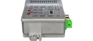
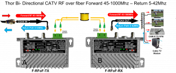 Transmisor y Receptor RF CATV Bidireccional para Cable Coaxial por Fibra - 45-1000 MHz Camino Directo y 5-42 MHz Camino de Retor
Cable coaxial por fibra - Juego bidireccional CATV por fibra diseñado para reemplazar cable coaxial punto a punto. Proporciona servicio sobre cable coaxial con dos componentes diferentes (CATV + Internet).
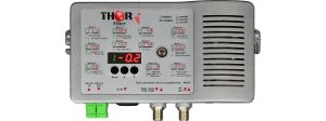
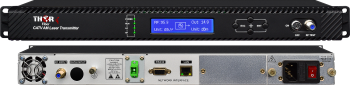 Transmisor RF CATV por Fibra Óptica 4 mW 45-870 MHz
Transmisor de RF por fibra óptica de 4 mW para señales portadoras de televisión o cualquier otra señal RF en la banda de 45-870 MHz. Transmite señales de banda completa con respuesta lineal.
 EN
EN


