 EN
EN


Divisor 1x2 F-PLC-1x2
| Disponibilidad: | En stock | Condición: | nuevo |
|
| Envío: | starting at $0.00 | Garantía: | 2Yrs |
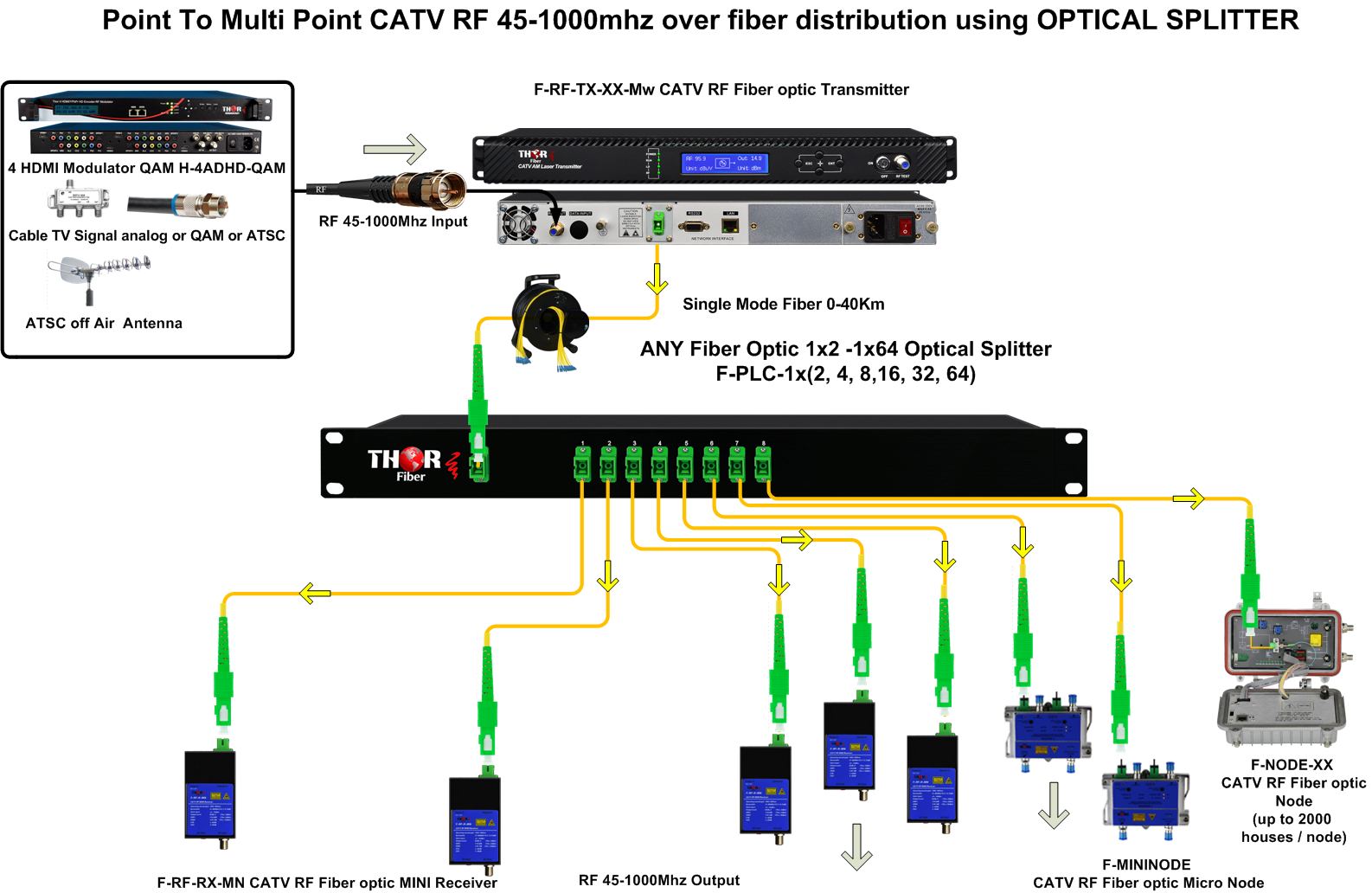
El divisor de fibra óptica es un dispositivo óptico pasivo que puede dividir o separar un haz de luz incidente en varios haces de luz en una proporción determinada.
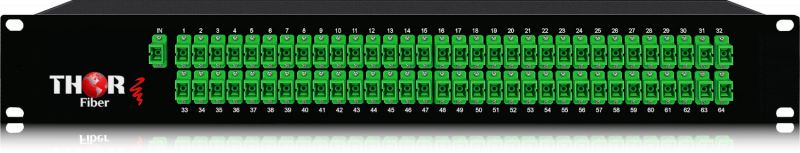
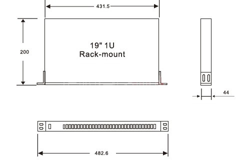
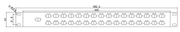
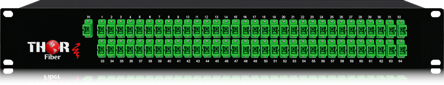
Divisores PLC para montaje en rack 1U tipo 1x2, 1x4, 1x8, 1x16, 1x32, 1x64 y
Divisores PLC para montaje en rack 1U tipo 2x2, 2x4, 2x8, 2x16, 2x32, 2x64.
Existen cuatro tipos de conectores de fibra óptica ampliamente usados para terminar fibras individuales. Son los conectores LC, SC, ST y FC. El conector LC tiene una férula cerámica de 1,25 mm, que es solo la mitad del tamaño de otros conectores. Es un conector de encaje rápido, usualmente usado para aplicaciones de alta densidad. El conector SC utiliza una férula cerámica de 2,5 mm y también cuenta con conexión de encaje rápido para parcheo rápido de cables. A diferencia de otros conectores, el conector ST usa una conexión de bayoneta con giro y una férula de 2,5 mm. Además, el FC es un conector de tipo rosca con férula de 2,5 mm, pero está siendo menos popular que los conectores LC y SC. Este divisor de fibra óptica/acoplador de fibra ofrece la señal de la más alta calidad.
Al terminar la fibra óptica con un conector, también debe decidir el tipo de pulido si el conector no está pulido previamente. Generalmente, la cara final del conector se pule para minimizar la reflexión de luz hacia atrás. Usando estilos de pulido compatibles, la luz puede propagarse a través de los conectores con menor pérdida en la fibra. Hay cuatro tipos de estilos de pulido: plano, PC, UPC y APC. Entre ellos, los tipos UPC y APC son más populares en la industria. La diferencia principal entre los conectores UPC y APC es que el tipo APC se pule con un ángulo de 8 grados mientras que el UPC no tiene ángulo, pero ambos son ligeramente curvados para mejor alineación del núcleo. En cuanto al color, el conector UPC suele ser azul y el APC verde. Nuestro divisor de fibra proporciona la transferencia de datos de la más alta calidad disponible.
 |
 |
Tenga en cuenta que cada acoplador divisor óptico 1xN tiene su propia PÉRDIDA DE INSERCIÓN específica.
Es la pérdida de potencia de señal resultante de la inserción de un dispositivo en una línea de transmisión o fibra óptica y usualmente se expresa en decibelios (dB). La tabla de pérdidas a continuación describe la pérdida de señal para cada tipo.
Divisor 1x2 F-PLC-1x2
Divisor 1x4 F-PLC-1x4
Divisor 1x8 F-PLC-1x8
Divisor 1x16 F-PLC-1x16
Divisor 1x32 F-PLC-1x32
Divisor 1x64 F-PLC-1x64
PÉRDIDA DE INSERCIÓN 4dB
7.3dB
10.5dB
13.8dB
16.8dB
20.5dB
|
Acopladores ópticos de fibra para montaje en rack 1x2 Pérdida de inserción 4dB |
F-PLC-1x2 |  |
|
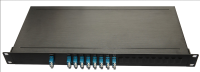
Acopladores ópticos compactos LGX de fibra 1x2 Pérdida de inserción 4dB |
F-PLC-1x2-LGX |  |
|
Acopladores ópticos de fibra para montaje en rack 1x4 Pérdida de inserción 7.4dB |
F-PLC-1x4 |  |
|
Acopladores ópticos compactos LGX de fibra 1x4 Pérdida de inserción 7.4dB |
F-PLC-1x4-LGX |  |
|
Acopladores ópticos de fibra para montaje en rack 1x8 Pérdida de inserción 10.5dB |
F-PLC-1x8 |  |
|
Acopladores ópticos de fibra para montaje en rack 1x16 Pérdida de inserción 13.8dB |
F-PLC-1x16 |  |
|
Acopladores ópticos de fibra para montaje en rack 1x32 Pérdida de inserción 16.7dB |
F-PLC-1x32 |  |
XX : SC/PC, SC/APC, ST/PC, ST/APC, LC/PC, LC/APC, FC/PC, FC/APC

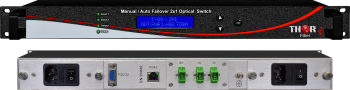 Conmutador Gestionado de Fibra Óptica
Conmutador gestionado de fibra óptica para redundancia del sistema
 Multiplexor por División en Longitud de Onda WDM
Unidades de multiplexor por división en longitud de onda para aplicaciones WDM, CWDM o DWDM. También podemos personalizar nuestro equipo para su uso con estas ópticas.
