| Availability: | Check availability | Condition: | new |
|
| Shipping: | starting at $0.00 | Warranty: | 2Yrs |
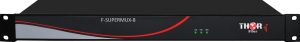
PN : F-SUPERMUX-8
1~8 Channel Universal platform for multiplexing SD/HD 3G SDI, DVB-ASI, Analog CVBS Video, Analog Audio, AES/EBU Audio, RS Data, 10/100 and Gigabit Ethernet
It is designed as a modular system to support up to 8 3G/HD/SD-SDI, up to 4 gigabit Ethernet, up to 8 XLR interfaces for unidirectional analog audio or AES/EBU digital audio, up to 16 phoenix terminal groups for audio, RS232, RS422, RS485 and contact closure, and up to 2 optical wavelength signals for external devices. It can be widely used in TV live broadcast, high-definition video conference, high-definition video monitoring, intelligent transportation systems, and public security systems.
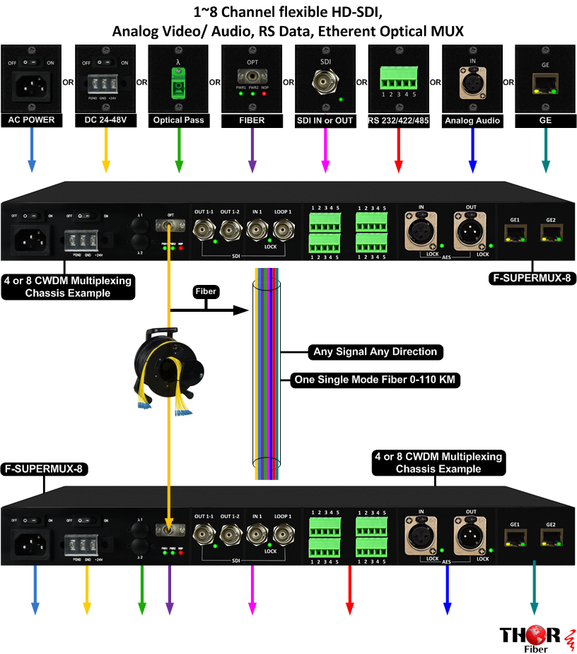
Part Number : F-SUPERMUX -X , ( X= 1 to 8 - the number of siganals multiplexed, - the number of optical CWDM wavelengths λ used )
Technical Specification
|
Item |
Typical Value |
|
SDI Interface |
|
|
Connector |
BNC |
|
Bit rate |
2970Mb/s, 1485Mb/s and 270Mb/s auto adaptive |
|
Standard |
Comply with SMPTE-424M 3G-SDI,SMPTE-292M HD-SDI and SMPTE-259M SD-SDI |
|
Impedance |
75Ω |
|
Return loss |
>15dB |
|
Output level |
800mVp-p±10% |
|
Rise and fall time (3G-SDI) |
≤135ps |
|
Rise and fall time(HD-SDI) |
≤270ps |
|
Rise and fall time(SD-SDI) |
≤1.50ns |
|
SD-SDI alignment jitter (1KHz) |
≤0.2UI |
|
SD-SDI timing jitter (10Hz) |
≤0.2UI |
|
HD-SDI alignment jitter (100KHz) |
≤0.2UI |
|
HD-SDI timing jitter (10Hz) |
<1.0UI |
|
3G-SDI alignment jitter(100KHz) |
≤0.3UI |
|
3G-SDI timing jitter(10Hz) |
≤2.0UI |
|
Optical Interface |
|
|
Connector |
Optional SC / FC / ST-PC connector - (per request) |
|
Distance |
40Km |
|
Receive sensitivity |
-21dBm |
|
Overload optical power |
0dbm |
|
Sending optical power |
-3~+3dBm |
|
Connector of cascaded ports |
Optional SC/FC/ST-PC connector |
|
GE Interface |
|
|
Connector |
RJ45 |
|
Frame length |
From 64 to 2036 bytes |
|
Default working mode |
Auto-negotiation |
|
Bit rate |
10/100/1000Mb/s |
|
Duplex |
Half/full duplex |
|
Flow Control |
Enable as default |
|
Standard |
IEEE802.3ab 1000Base-T / IEEE802.3u 100Base-TX / IEEE802.3 10Base-T |
|
Analog Audio Interface |
|
|
Connector |
Phoenix connector |
|
Input impedance |
10KΩ |
|
Output impedance |
75Ω |
|
Sample rate |
48KHz |
|
Coding bits |
24 bit |
|
Input/output level |
2Vp-p |
|
RS485 Interface |
|
|
Connector |
Phoenix connector |
|
Baud rate |
0~115.2Kbps |
|
Working mode |
Bi-direction, half duplex |
|
RS422/RS232 Interface |
|
|
Connector |
Phoenix connector |
|
Baud rate |
0~115.2Kbps |
|
Working mode |
Bi-direction, full duplex |
|
XLR Interface |
|
|
Connector |
XLR |
|
The maximum differential input level |
+18dBu |
|
Impedance |
Input impedance : 2.2KΩ@1KHz |
|
Power Supply |
|
|
Power supply |
AC220 /DC48 /DC24V |
|
220VAC input voltage range |
100~240V AC |
|
48VDC input voltage range |
36~72V DC |
|
24VDC input voltage range |
18~36V DC |
|
Environment Requirements |
|
|
Working temperature |
-30~60°C |
|
Relative Humidity |
≤95%, no condensation |
|
Storage temperature |
-40~85°C |
|
Mechanical Dimension |
|
|
Dimension |
482mm(L)×44mm(H)×250mm(W) |
Note:
1. The default transmission distance is 40Km. Please declare when ordering if longer distance is required.
2. In order to prevent the damage of optical modules, an attenuator(10dB in general) must be inserted into the short fiber tail that sometimes used to connects the two devices for test purposes.
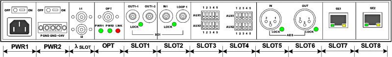
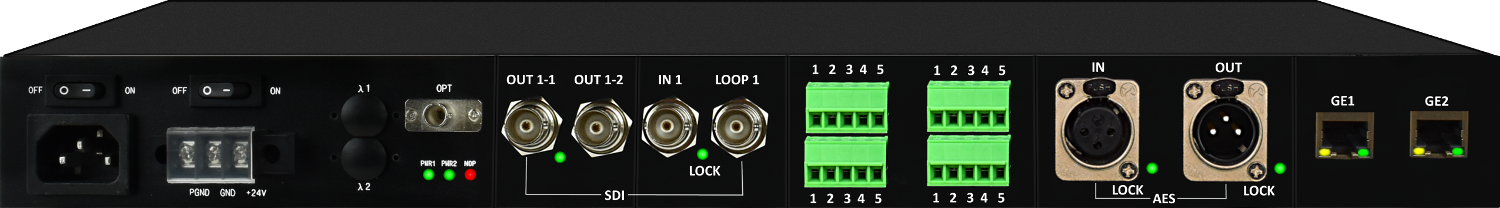
Slots on Rear Panel
| MODULE | SLOT | |||||||||||
| Item | MAX | PWR1 | PWR2 | λSLOT | SLOT1 | SLOT2 | SLOT3 | SLOT4 | SLOT5 | SLOT6 | SLOT7 | SLOT8 |
| AC220V | 2 | YES | YES | NO | NO | NO | NO | NO | NO | NO | NO | NO |
| DC48V | 2 | YES | YES | NO | NO | NO | NO | NO | NO | NO | NO | NO |
| DC24V | 2 | YES | YES | NO | NO | NO | NO | NO | NO | NO | NO | NO |
|
λ |
1 | NO | NO | YES | NO | NO | NO | NO | NO | NO | NO | NO |
| SDI or ASI IN | 8 | NO | NO | YES | YES | YES | YES | YES | YES | YES | YES | YES |
| SDI or ASI OUT | 8 | NO | NO | YES | YES | YES | YES | YES | YES | YES | YES | YES |
| XLR IN/OUT | 4 | NO | NO | NO | YES | YES | YES | YES | YES | YES | YES | YES |
| GIGABIT ETHERNET | 4 | NO | NO | NO | NO | NO | NO | NO | NO | NO | NO | NO |
| 5 PIN INDUSTRIAL TERMINAL | 4 | NO | NO | NO | NO | NO | NO | NO | NO | NO | NO | NO |
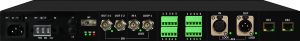
Interfaces on Rear Panel
|
Name |
Description |
||
|
OPT |
Common optical interface, bi-directional, FC / SC / ST-PC can be selected. |
||
|
l1-l2 |
Optional cascade optical interfaces. l1-l2 are wavelength division multiplexed into the common optical interface. The wavelength should be described in the order item. l1 will be the shorter wavelength, and l2 will be the longer wavelength. |
||
|
SDI IN |
3G/HD/SD-SDI input. |
||
|
SDI LOOP |
Optional 3G/HD/SD-SDI loop out. |
||
|
SDI OUT1 |
3G/HD/SD-SDI output 1. |
||
|
SDI OUT2 |
Optional 3G/HD/SD-SDI output 2. |
||
|
ETH 10/100/1000M |
Gigabit Ethernet |
||
|
AUX1/AUX2 |
Auxiliary service interfaces. Every five terminals are used as a group, and the service type can be configured for each group independently, including audio, RS232, RS422, RS485, and contact closure. See details. |
||
|
Power |
Supports 220VAC/110VAC, 48VDC or 24V DC power supply. Any two of them can be selected and installed. |
||
|
~220V AC |
~220V |
AC power input. 100VAC~240VAC |
|
|
-48V DC |
PGND |
Earth ground (connects to the chassis). |
|
|
GND |
Ground |
||
|
-48V |
48VDC. 36VDC ~72VDC. |
||
|
+24V DC |
PGND |
Earth ground (connects to the chassis). |
|
|
GND |
Ground |
||
|
+24V |
24VDC power. 18VDC~36VDC. |
||
Rear Panel
|
1-channel bi-directional RS422 AUX204 (Transmitter) |
Signal Direction |
1-channel bi-directional RS422 AUX204 (Receiver) |
||||
|
Description |
No. |
Pin Name |
Pin Name |
No. |
Description |
|
|
Differential signal output A |
1 |
OUTA |
|
INA |
1 |
Differential signal input A |
|
Differential signal output B |
2 |
OUTB |
INB |
2 |
Differential signal input B |
|
|
Differential signal input A |
3 |
INA |
|
OUTA |
3 |
Differential signal output A |
|
Differential signal input B |
4 |
INB |
OUTB |
4 |
Differential signal output B | |
|
Ground |
5 |
G |
G |
5 |
Ground |
|
Indicators on Rear Panel
|
Name |
Description |
|
LINK |
Optical port status indicator. RED/GREEN. RED ON: Optical signal loss is detected at the port. GREEN ON: Normal. |
|
PWR1,PWR2 |
Power1/Power2 indicators, GREEN ON: the power works normally OFF: the power is abnormal or absent. |
|
LOCK |
SDI input/output lock indicator, GREEN. ON: SDI input/output normal. OFF: SDI input/output abnormal. |
|
ETH GREEN |
Ethernet link/active indicator, GREEN. ON: Normal link but no data transmit or receive; BLINK: Normal link and there is data transmitting and receiving; OFF: No link or the interface is damaged |
|
ETH YELLOW |
Ethernet speed indicator, YELLOW. For ETH 10/100/1000M, ON: operating at 1000Mb/s OFF: operating at 100/10Mb/s |
AUX on Rear Panel
| AUX interface | No. | Pin Name | Description | |
|
2-channel bi-directional audio AUX213 |
1 | OUT 1 | Audio channel - 1 output |
Use AUX213-AUX213 in pairs |
| 2 | OUT 2 |
Audio channel - 2 output |
||
| 3 | G | Ground | ||
| 4 | IN 1 | Audio channel - 1 input | ||
| 5 | IN2 | Audio channel - 2 output | ||
| 4-channel unidirectional audio Input AUX211 | 1 | IN 1 | Audio channel - 1 input |
Use AUX211-AUX212 in pairs |
| 2 | IN 2 |
Audio channel - 2 output |
||
| 3 | G | Ground | ||
| 4 | IN 3 |
Audio channel - 3 input |
||
| 5 | IN 4 |
Audio channel - 4 input |
||
|
4-channel unidirectional audio Output AUX212 |
1 | OUT 1 |
Audio channel - 1 output |
|
| 2 | OUT 2 |
Audio channel - 2 output |
||
| 3 | G | Ground | ||
| 4 | OUT 3 |
Audio channel - 3 output |
||
| 5 | OUT 4 |
Audio channel - 4 output |
||
|
4-channel unidirectional audio Output AUX208 |
1 | IN 1 |
Audio channel - 1 input |
Use AUX207-AUX208 in pairs |
| 2 | IN 2 |
Audio channel - 2 input |
||
| 3 | G | Ground | ||
| 4 | - | - | ||
| 5 | - | - | ||
|
2-channel unidirectional audio Input AUX207 |
1 | OUT 1 |
Audio channel - 1 output |
|
| 2 | OUT 2 |
Audio channel - 2 output |
||
| 3 | G | Ground | ||
| 4 | - | - | ||
| 5 | - | - | ||
|
2-channel contact closure input AUX201 |
1 | IN1 | The first-channel contact closure input |
Use AUX200-AUX201 in pairs |
| 2 | COM1 | Command contact of the first-channel contact closure | ||
| 3 | IN2 | The second-channel contact closure input | ||
| 4 | COM2 | Command contact of the second-channel contact closure | ||
| 5 | - | - | ||
|
2-channel contact closure output AUX200 |
1 | OUT1 | The first-channel contact closure output No alarm: the contact is normally closed (NC) Alarm: the contact is open |
|
| 2 | COM1 | Command contact of the first-channel contact closure | ||
| 3 | OUT2 | The second-channel contact closure output No alarm: the contact is normally closed (NC) Alarm: the contact is open |
||
| 4 | COM2 | Command contact of the second-channel contact closure | ||
| 5 | - | - | ||
|
2-channel bi-directional RS485 AUX204 |
1 | A1 | RS485 channel 1 differential signal A |
Use AUX204-AUX204 in pairs |
| 2 | B2 | RS485 channel 1 differential signal B | ||
| 3 | A2 | RS485 channel 2 differential signal A | ||
| 4 | B2 | RS485 channel 2 differential signal B | ||
| 5 | G |
Ground |
||
|
2-channel bi-directional RS232 |
1 | OUT 1 | RS232 signal output 1 |
Use AUX205-AUX205 in pairs |
| 2 | IN 1 | RS232 signal input 1 | ||
| 3 | G | Ground | ||
| 4 | OUT 2 | RS232 signal output 2 | ||
| 5 | IN 2 | RS232 signal input 2 |
Unfortunately, we cannot accommodate a 10G Fiber or Copper interface since we do not currently have this card available for this system.
However, since the unit utilizes CWDM optical muxing, we can offer a CWDM pass-through interface.
For example, we can provide two open optical ports, such as 1470nm and 1490nm, allowing you to pass any signal within those wavelengths. If your 10Gb switches have 10G SFPs, one at 1470nm and the second at 1490nm, we can seamlessly pass the signal across.
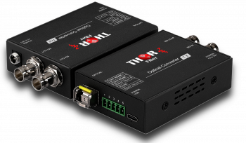 12G-SDI fiber extender with return RS485 and 2-Channel Reverse Tally
1-channel 12G-SDI with loop-out, 1-channel reverse RS485 data, and 2-channel reverse Tally (one red and one green). The system supports bidirectional multi-service transmission over a single optical fiber, enabling lossless, delay-free transmission up to 20 km. Designed for broadcast and production environments requiring long-distance SD/HD/3G/12G-SDI video transport with integrated camera control and tally feedback. Suitable for OB vans, studio-camera links, live event coverage, and remote production systems.
 4 x (4K/UHD) at 30 fts or 2 x 4K @60 fps over fiber converter
2-channel 4K/UHD signals at 60 fps. 4-channel 4K/UHD resolutions at 30 fps. 8 channels of independent 3G/HD/SD-SDI or DVB-ASI.
 ES
ES


