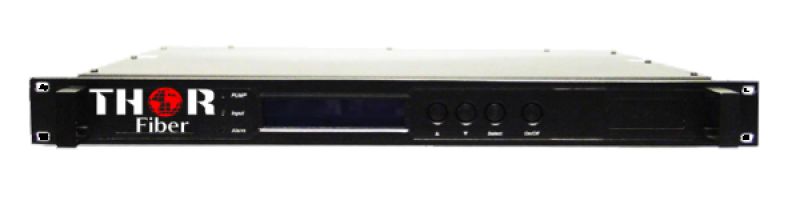
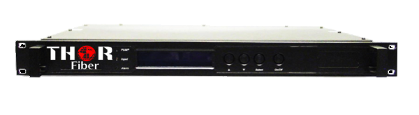
| Availability: | Check availability | Condition: | new |
|
| Shipping: | starting at $0.00 | Warranty: | 2Yrs |
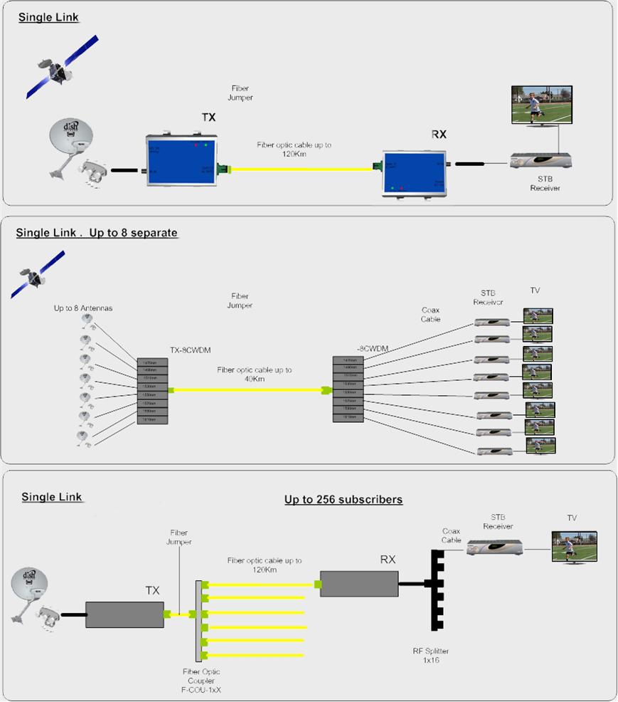
The F-KuBAND is used to transmit and receive uplink and downlink signals up to 15 GHz. This is useful for links between control rooms or NOCs. The F-KuBAND system offers a high-performance alternative to conventional coaxial link systems, both reducing attenuation and eliminating the need for a waveguide. The unit functions as a transparent link, transporting all satellite modulation formats over a single fiber. Typically, a Ku-Band fiber link consists of an optical transmitter that receives the RF signal and transmits it over single-mode fiber to an optical receiver, which converts the optical signal back to RF. When used in CWDM configurations, the F-KuBAND is able to transmit up to 8 independent satellite signals over a single fiber. The F-KuBAND link is a cost-effective and high-performance solution for Ku-Band over fiber satellite links.
- Useful Bandwidth up to 15 GHz
- Ku-Band Over Fiber for links up to 120 km
- Highly Linear for Analog Transmission
- Low RIN, Narrow Linewidth DFB Laser
- Broadband LiNbO3 Modulator
- Linear PIN receiver with TIA
- Optional single port design allows Bi-directional Transmission with 1 fiber
- Optional RF amplifier to enhance gain
IMPORTANT NOTE*** (It is very important to interface our unit with an SC/APC - Angle Polished Connector to avoid any light reflections.)
If your fiber is terminated with the SC, ST, FC/PC flat connector, you need to use an optical jumper from PC type to SC/APC for proper conversion.
|
Model Number |
Description |
|
Ku-BAND Singlemode Fiber Transmitter for 10km |
|
Ku-BAND Singlemode Fiber Reciever for 10km |
|
Ku-BAND Singlemode Fiber Transmitter for 40km |
|
Ku-BAND Singlemode Fiber Reciever for 40km |
|
Ku-BAND Singlemode Fiber Transmitter for 80km |
|
Ku-BAND Singlemode Fiber Reciever for 80km |
|
Ku-BAND Singlemode Fiber Transmitter for 120km |
|
Ku-BAND Singlemode Fiber Reciever for 120km |
|
*All Specifications Subject to Change Without Notice IMPORTANT NOTE*** (it is very important to interface our unit with SC/APC - Angle Polished Connector to avoid any light reflections.) If your fiber is terminated with the SC, ST, FC/PC flat connector, you need to use an optical jumper from PC type to SC/APC for proper conversion. |
|||
|
10.0 - 15.0 GHz |
||
|
>70 dB |
||
|
+/- 0.2 dB / 48 MHz |
||
|
-50 dBc (max.), -55 dBc (typ.) |
||
|
(36 MHz BW) >50 dBc |
||
|
Input Signal |
|
||
|
-25 to -40 dBm |
||
|
-10 to -40 dBm |
||
|
+/- 0.15 dB / 24 hours |
||
|
|
||
|
-15 to 0 dBm (typ.) |
||
|
0 to +15 dBm (typ.) |
||
|
Noise Figure @ max input gain |
|
||
|
<22 dB (typ.) |
||
|
<9 dB (typ.) |
||
|
Peak-to-peak 0.4 ns (typ.) |
||
|
50 Ohm |
||
|
1.4:1 |
||
|
Maximum RF Input (with no damage) |
|
||
|
-10 dBm |
||
|
+5 dBm |
||
|
Standard |
||
|
20 dB +/- 1.0 |
||
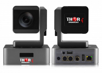 PTZ 20x Zoom Streaming HD Camera with SDI-HDMI-USB Outputs - MaximusProFly
The Thor broadcast-quality MaximusProFly video PTZ camera has advanced video image processing technology and a Full HD CMOS sensor with multiple video output formats. Max resolution up to 1080P60FPS; approx. 2.38 Megapixel picture presentation, true-color image quality. Frame rate: 1080P60/59.94/50/30/29.97/25; 1080I60/59.94/50/30/29.97/25; 720P60/50/30/25, 480I60, 576I50 Easy direct RTMP RTSP streaming to services like YouTube, Facebook, Twitch, or Wowza; for church live streaming setup, or similar. The camera can be controlled by a web interface or the included remote control.
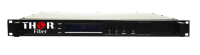 K-BAND over Fiber
K-Band RF over fiber optic cable transport system. Can be customized for transport distances of up to 150 Km. Can also provide LNB power at various voltages.

 ES
ES