| Availability: | Check availability | Condition: | new |
|
| Shipping: | starting at $0.00 | Warranty: | 1Yrs |
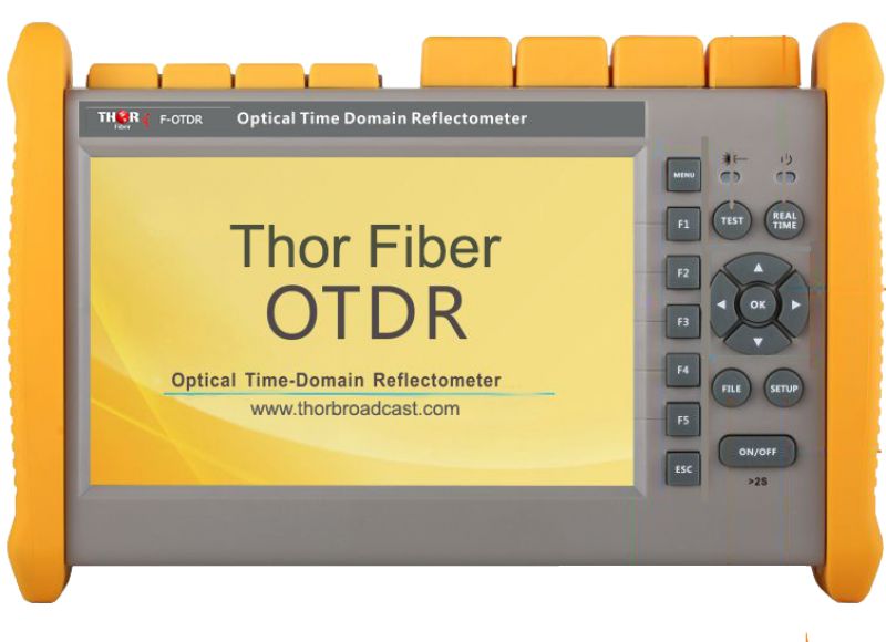
An Optical Time Domain Reflectometer sends out a flash of bright light and measures the intensity of echoes or reflections. This weak signal is averaged to reduce detection noise, and computation is used to display faults and measure losses caused by bends, splicing, or connectors.
This instrument is for measuring point loss on installed systems, where it is used to find faults and measure point losses such as those caused by splicing. However, doing this accurately is more complicated and time-consuming than is commonly supposed, since a measurement should be taken from both ends of the system and then averaged. If this is not done, spurious excess losses and "gainers" may be recorded where different fibers are joined, resulting in wasted splicing effort while non-existent faults are "repaired". This is a particular issue when measuring fusion splice joints, where the loss is small and the adjacent sections may have fibers with different intrinsic backscatter characteristics.
Ideally, OTDRs are used for return loss measurements.
APPLICATIONS

 Thor fiber")
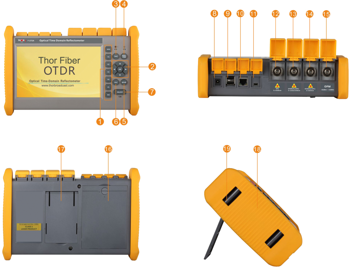
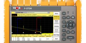
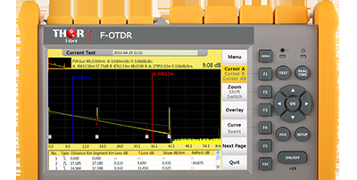
Test Interface
Quick fit in short time
Simplified display style and structured menus help reduce study time.
FTTH test within PON networks
Last mile master
F-OTDR series OTDR can easily test through a 1x32 PLC splitter in PON testing (Model: F-OTDR-T43F).
General
|
253x168x73.6mm 1.5kg (battery included) |
|
7 inch TFT-LCD with LED backlight (touchscreen function is optional) |
|
1x RJ45 port, 3x USB ports (USB 2.0, Type A USBx2, Type B USBx1) |
|
10V(dc), 100V(ac) to 240V(ac), 50~60Hz |
|
7.4V(dc)/4.4Ah lithium battery (with air traffic certification) Operating time: 12 hours; Telcordia GR-196-CORE Charging time: <4 hours (power off) |
|
Backlight off: Disable/1 to 99 minutes Auto shutdown: Disable/1 to 99 minutes |
|
Internal memory: 4GB (about 40,000 groups of curves) |
|
User selectable |
|
Operating temperature and humidity: -10?~+50?, <=95% (non-condensation) Storage temperature and humidity: -20?~+75?, <=95% (non-condensation) Protection: IP65 (IEC60529) |
|
Standard: Main unit, power adapter, lithium battery, FC adapter, USB cord, User guide, CD disk, carrying case Optional: SC/ST/LC adapter, bare fiber adapter |
Technical parameter
| Type | Testing Wavelength (MM: +/-20nm, SM: +/-10nm) |
Dynamic Range (dB) | Event/Attenuation Dead-zone (m) |
|
850/1300 1310/1550 |
19/21 40/38 |
0.8/4 1/4 |
|
1310/1550/1625 | 43/41/41 | 1/5 |
Test parameter
|
Single mode: 3ns, 5ns, 10ns, 20ns, 50ns, 100ns, 200ns, 500ns, 1us, 2us, 5us, 10us, 20us Multi-mode: 3ns, 5ns, 10ns, 20ns, 50ns, 100ns, 200ns, 500ns, 1us, 2us |
|
Single mode: 100m, 500m, 2km, 5km, 10km, 20km, 40km, 80km, 120km, 160km, 240km Multi-mode: 500m, 2km, 5km, 10km, 20km, 40km |
|
Minimum 5cm |
|
Maximum 128,000 points |
|
<=0.05dB/dB |
|
X axis: 4m~70m/div, Y axis: Minimum 0.09dB/div |
|
0.01m |
|
+/-(1m+measuring distancex3x10-5+sampling resolution) (excluding IOR uncertainty) |
|
Single mode: +/-2dB, multi-mode: +/-4dB |
|
1.4000~1.7000, 0.0001 step |
|
Km, miles, feet |
|
Telcordia universal, SOR, issue 2 (SR-4731) OTDR: User selectable automatic or manual set-up |
|
Visual fault locator: Visible red light for fiber identification and troubleshooting Light source: Stabilized Light Source (CW, 270Hz, 1kHz, 2kHz output) Field microscope probe |
|
-Reflective and non-reflective events: 0.01 to 1.99dB (0.01dB steps) -Reflective: 0.01 to 32dB (0.01dB steps) -Fiber end/break: 3 to 20dB (1dB steps) |
|
Real-time sweep: 1Hz Averaging modes: Timed (1 to 3600 sec.) Live Fiber detect: Verifies the presence of communication light in optical fiber Trace overlay and comparison |
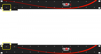 Mounting L Brackets for H-HDMI-RF-PETIT to mount multiple Modulators in 19" rack
Individual Petit modulator mounting L brackets - accessory to mount multiple modulators in a 19" rack
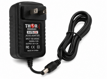 5V DC 2A Power Supply Adapter with 5.5mm x 2.1mm Barrel Connector for Thor fiber and Broadcast Products
5V DC 2A regulated power supply for Thor Fiber and Broadcast products. Includes 5.5mm x 2.1mm center-positive barrel connector and universal 100-240VAC input. Part number: H-PS-5V.
 ES
ES


