Learn how to distribute 30+ HD TV channels to 16 buildings using HDMI to Clear QAM modulators, a 32 mW CATV RF fiber transmitter, 1x16 optical splitter, and RF fiber receivers-without replacing existing coax or installing a set-top box at every TV.
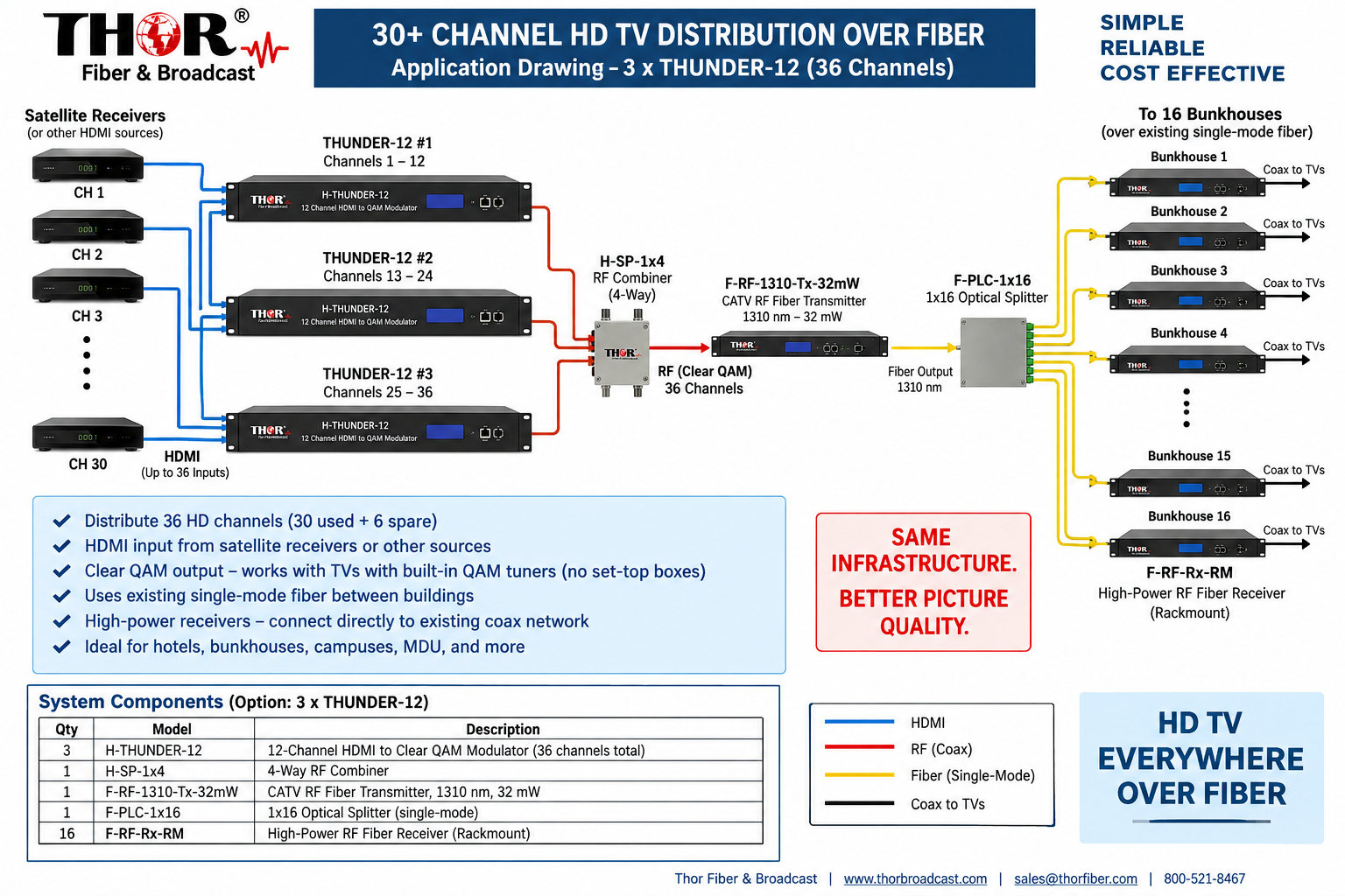
Table of Contents
This is a common problem in large remote camps, hotels, dormitories, hospitals, correctional facilities, mining camps, military facilities, campuses, and other multi-building properties.
A facility may have dozens of satellite or cable receivers installed in a central headend. Each receiver provides one television program, and older analog modulators convert those programs into RF channels that are combined and distributed over coaxial cable.
The system may have worked reliably for many years, but eventually several problems begin to appear:
The analog modulators are aging. Picture quality is limited. Equipment begins to fail. The facility wants HD digital television. Fiber has already been installed between buildings, but hundreds of existing coaxial TV drops are still in place inside the buildings.
Replacing all of that coax with Ethernet or fiber can become a very expensive project.
Fortunately, it usually isn’t necessary.
Thor Fiber and Broadcast can combine HDMI to Clear QAM modulation with RF over fiber transport, allowing the facility to upgrade the headend to digital HD while continuing to use both its existing single-mode fiber backbone and existing coaxial TV distribution network.
The result is a modern digital television system without requiring an IPTV box or set-top box at every television.
Consider a remote facility operating approximately 30 television channels.
The original system uses individual satellite receivers feeding older analog RF modulators. Those RF channels are combined and distributed to multiple bunkhouses.
Each bunkhouse contains approximately 40–50 televisions.
The facility already has a major advantage: dedicated single-mode fiber has been installed from the central data room to each bunkhouse in a star topology.
However, inside each bunkhouse, coaxial cable already reaches all of the televisions.
Instead of abandoning that infrastructure, we can use it.
The proposed Thor Fiber and Broadcast architecture is:
30 Satellite Receivers → HDMI → Digital Clear QAM Modulators → RF Combiner → CATV RF Fiber Transmitter → 1×16 Optical Splitter → Existing Single-Mode Fiber → RF Fiber Receiver at Each Building → Existing Coax → TVs
This approach provides a relatively simple migration from an aging analog CATV system to a modern HD digital television distribution network.
The first step is replacing the old analog modulators.
Modern satellite receivers, cable receivers, media players and similar sources normally provide HDMI output. Rather than converting those sources back into analog NTSC video, the HDMI signal can be encoded and converted directly into digital RF television channels.
For this 30-channel application, we use:
3 × H-THUNDER-12 HDMI to QAM Modulators
Thor H-THUNDER-12 12-Channel HDMI to QAM RF Modulator
Each H-THUNDER-12 accepts up to 12 HDMI sources, allowing three units to accommodate as many as 36 HDMI programs. The product supports Full HD sources and MPEG-2 encoding and creates digital RF channels suitable for CATV distribution. (Thor Broadcast)
For this particular system:
H-THUNDER-12 #1: Channels 1–12 H-THUNDER-12 #2: Channels 13–24 H-THUNDER-12 #3: Channels 25–36
Only 30 inputs are initially required, so the system has capacity for:
30 active TV channels + 6 spare HDMI inputs
Those six additional inputs provide useful expansion capacity.
A future local information channel, security camera, digital signage player, additional satellite receiver, entertainment channel or other HDMI source could be added without replacing the headend hardware.
Moving from analog modulation to digital Clear QAM provides several important advantages.
First, the facility can distribute HD digital programming rather than relying on aging analog video modulation.
Second, multiple digital television channels can coexist on the same coaxial distribution infrastructure.
Most importantly, a compatible television with an integrated Clear QAM tuner can tune the channels directly.
That means the architecture can remain:
Wall Coax Outlet → Television
rather than:
Wall Outlet → Set-Top Box → HDMI Cable → Television
For a facility containing hundreds of televisions, eliminating hundreds of additional receiver boxes can substantially simplify the installation.
There are fewer power supplies, remotes, HDMI cables and boxes in individual rooms to maintain.
Thor’s Thunder platform is specifically designed to turn HDMI sources such as satellite STBs and other video devices into digital RF channels that can be distributed through a conventional coaxial television network. (Thor Broadcast)
Once the HDMI sources have been converted to digital QAM RF, the RF outputs from the three H-THUNDER-12 units are combined.
The headend therefore becomes:
30 HDMI Sources ↓ 3 × H-THUNDER-12 ↓ RF Combiner ↓ One Combined Digital CATV RF Lineup
Each modulator is configured so that its RF output does not conflict with the others.
The combined RF output now carries the entire digital television lineup.
This is an important concept:
All of the television channels are already combined into one broadband CATV RF spectrum.
That entire spectrum is transported over a single optical fiber path to each remote building.
This is one reason RF over fiber works particularly well for large CATV distribution systems.
The combined RF output is connected to the:
F-RF-1310-TX-32mW High-Power CATV RF Over Fiber Transmitter
F-RF-1310-TX-32mW 32 mW CATV RF Over Fiber Transmitter
This is where the coaxial RF network becomes an optical network.
The F-RF-1310-TX-32mW accepts the broadband CATV RF input and converts it to a 1310 nm optical signal.
The transmitter provides 32 mW optical output and supports a 45–1000 MHz RF frequency range. Thor specifies support for signals including QAM J.83B, ATSC and traditional CATV formats. (Thor Broadcast)
The high optical output is particularly useful in this application because the signal must subsequently be divided among 16 separate fiber paths.
Instead of installing 16 individual optical transmitters, one high-power transmitter can feed the optical splitter.
The transmitter output connects to a:
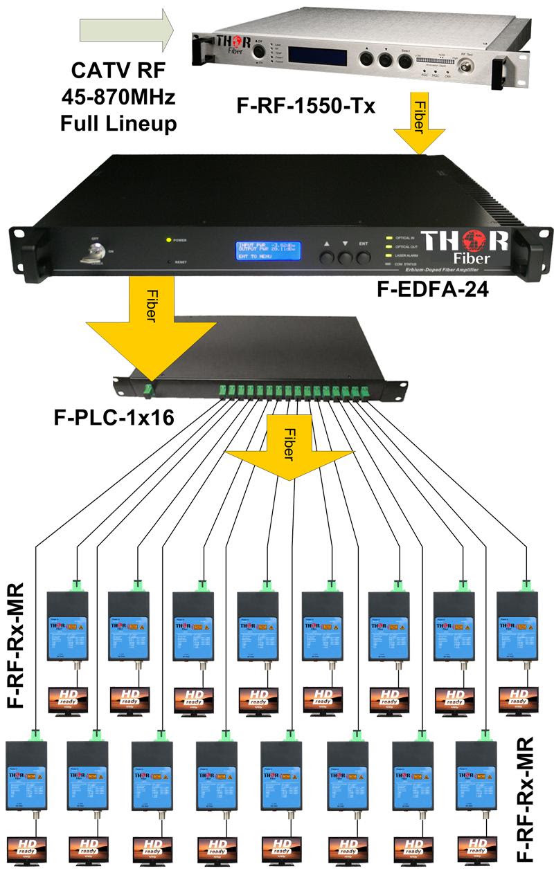
F-PLC-1×16 Single-Mode Fiber Optic PLC Splitter
Thor 1×16 Fiber Optic PLC Splitter
The splitter has a very simple job:
1 optical input → 16 optical outputs
Each output connects to the existing dedicated single-mode fiber serving one bunkhouse.
The architecture becomes:
32 mW RF Fiber Transmitter ↓ 1×16 PLC Optical Splitter ↙ ↓ ↓ ↓ ↓ ↘ 16 Single-Mode Fiber Home Runs ↓ 16 Bunkhouses
Thor’s 32 mW transmitter documentation specifically identifies PLC splitters in configurations including 1×8, 1×16, 1×32 and 1×64, and describes the combination of a high-power RF fiber transmitter, PLC splitter and remote RF receivers as an application architecture. (Thor Broadcast)
For this installation, the 1×16 configuration matches the required number of remote locations.
RF over fiber systems of this type are designed around single-mode optical fiber.
This is important when evaluating an existing facility.
The fiber backbone needs to be identified before selecting the optical equipment, and connector types should also be verified.
For this architecture, the recommended optical path is:
F-RF-1310-TX-32mW → F-PLC-1×16 → Existing Single-Mode Fiber → F-RF-RX-RM
Thor recommends matching SC/APC connections through the optical path for this transmitter/receiver architecture to minimize reflections. (Thor Broadcast)
The actual optical budget should always be verified using the installed fiber distance, splitter insertion loss, connector loss and any additional patch-panel or splice losses.
At each of the 16 bunkhouses, the fiber terminates at a:
F-RF-RX-RM High-Power Rackmount CATV RF Fiber Receiver
F-RF-RX-RM High-Power CATV RF Fiber Receiver
The receiver performs the opposite conversion from the transmitter:
Optical Fiber → Broadband CATV RF
Most importantly, it does not recover just one television program.
It recovers the entire RF channel lineup.
Therefore, the single RF coaxial output at the bunkhouse contains all of the Clear QAM television channels generated at the main headend.
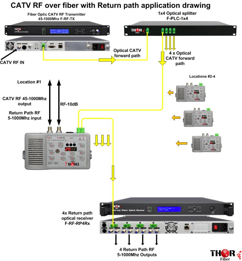
The output of the receiver can then feed the building’s existing coaxial distribution network.
This is where the design can provide significant installation savings.
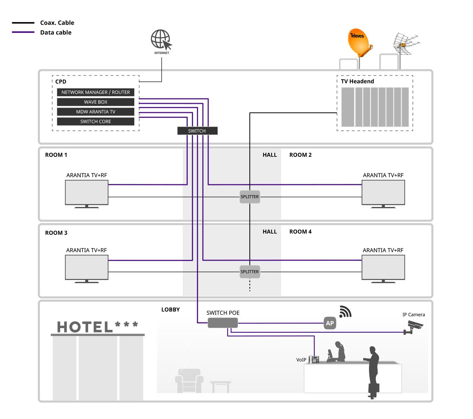
There may already be coaxial cable running through walls, ceilings and conduits to 40 or 50 televisions in every bunkhouse.
There is no reason to remove that infrastructure simply because the backbone has been upgraded to fiber.
At each building:
Existing Single-Mode Fiber ↓ F-RF-RX-RM ↓ RF Coax Output ↓ Existing CATV Splitters / Coax Network ↓ 40–50 TVs
The television performs a digital channel scan and discovers the available Clear QAM channels.
Users then change channels using the television’s normal remote control.
No IPTV client is required at every television.
No Ethernet cable has to be installed to every room.
And, assuming the televisions have compatible Clear QAM tuners, no separate QAM set-top box is required.
This concept sometimes causes confusion.
A facility might have 30 TV channels and 16 buildings, but that does not mean it needs 480 separate optical video links.
The channels are first converted to RF and combined.
The complete RF spectrum is then transported optically.
Think of the system as transporting the facility’s entire cable-TV network over fiber, rather than transporting individual HDMI cables.
That is why the architecture scales efficiently.
The headend creates the television network once.
The optical system then reproduces that network at every remote building.
Another advantage is centralized management.
All satellite receivers and HDMI modulators remain in the main data room.
Technicians do not have to visit 16 different bunkhouses every time a source needs to be changed.
The main equipment is located together:
Satellite / Cable Receivers H-THUNDER-12 Modulators RF Combining Equipment F-RF-1310-TX-32mW Fiber Transmitter
The Thunder family provides Ethernet/network management in addition to front-panel controls, allowing modulation parameters to be configured from the headend. (Thor Broadcast)
The remote buildings require only the optical receiver and their existing passive coaxial distribution equipment.
This makes the architecture particularly attractive for remote sites where the system may eventually be maintained by personnel who are not broadcast engineers.
Suppose Channel 14 is supplied by a satellite receiver.
That receiver fails.
With this centralized architecture, the technician goes to the headend and replaces the receiver feeding the corresponding HDMI input.
There is no need to visit hundreds of televisions.
Similarly, if the facility wants to add a new information channel, an HDMI signage player can be connected to one of the six unused HDMI inputs.
The channel is then added to the existing lineup and becomes available throughout the network.
Remote workforce camps and mining facilities have unusual television distribution requirements.
They can contain hundreds of rooms spread across multiple buildings while having a relatively small technical staff.
Traditional IPTV may require:
Ethernet infrastructure to every television, managed switches, IPTV middleware, individual decoders or compatible smart TVs, configuration of endpoints and additional network troubleshooting.
An RF-over-fiber/Clear-QAM architecture takes a different approach.
It uses fiber where fiber makes sense-between buildings-and coax where coax already exists-inside the buildings.
That makes it particularly useful when upgrading an established facility rather than designing a completely new building from scratch.
Although this example involves a remote camp, the architecture is applicable to many facilities.
Typical applications include hotels and resorts, university dormitories, hospitals, assisted-living facilities, apartment buildings and MDUs, military bases, correctional facilities, offshore facilities, mining camps, sports complexes, corporate campuses, schools, manufacturing facilities, cruise or maritime facilities, and other multi-building CATV networks.
The common requirement is the same:
A central group of HDMI video sources needs to be delivered to many televisions across a large facility while preserving existing coaxial infrastructure.
For the 30-channel / 16-building application described above, the proposed configuration is:
| QuantityModelFunction | ||
|---|---|---|
| 3 | H-THUNDER-12 | 12-Channel HDMI to Clear QAM Modulator |
| 1 | H-SP-1×4 | RF Combiner |
| 1 | F-RF-1310-TX-32mW | 32 mW 1310 nm CATV RF Fiber Transmitter |
| 1 | F-PLC-1×16 | 1×16 Single-Mode PLC Optical Splitter |
| 16 | F-RF-RX-RM | High-Power Rackmount CATV RF Fiber Receiver |
The resulting signal path is:
30 Satellite/Cable Receivers ↓ HDMI 3 × H-THUNDER-12 ↓ Clear QAM RF RF Combiner ↓ F-RF-1310-TX-32mW ↓ 1310 nm Fiber F-PLC-1×16 Optical Splitter ↓ 16 Existing Single-Mode Fiber Runs ↓ 16 × F-RF-RX-RM ↓ RF Coax Existing Building CATV Networks ↓ Hundreds of Televisions
Perhaps the biggest advantage of this approach is what doesn’t need to change.
The facility doesn’t necessarily need to replace the coaxial cabling already installed to every room.
It doesn’t necessarily need to install an IPTV receiver behind every television.
It doesn’t need 30 separate fibers to every building.
Instead, the upgrade is concentrated around the parts of the network where modernization provides the greatest benefit:
HDMI digital sources → digital Clear QAM headend → high-power RF over fiber backbone.
At the remote end, the system converts back to conventional CATV RF so the existing distribution infrastructure can continue doing its job.
Same infrastructure. Better picture quality. A much more modern headend.
Every facility is slightly different.
Before specifying an RF-over-fiber distribution system, Thor Fiber and Broadcast normally needs to know:
How many HDMI/video channels are required? How many buildings or fiber endpoints are there? What type of fiber is installed? What are the approximate fiber distances? What connector types are used? How many TVs are located at each endpoint? What coaxial distribution equipment already exists? Do the televisions support Clear QAM?
From that information, the optical budget and appropriate transmitter, splitter and receiver configuration can be determined.
For installations with approximately 30 HDMI sources and up to 16 remote locations, the combination of H-THUNDER-12 HDMI modulators, a high-power F-RF-1310-TX-32mW transmitter, PLC optical splitting and F-RF-RX-RM receivers provides a straightforward way to bridge a digital CATV headend with an existing fiber-and-coax infrastructure. Thor’s own 32 mW transmitter application guidance describes this same fundamental transmitter → PLC splitter → RF receiver topology. (Thor Broadcast)
H-THUNDER-12 – 12 HDMI to Clear QAM RF Modulator
F-RF-1310-TX-32mW – 32 mW CATV RF Over Fiber Transmitter

 ES
ES