Design RF over Fiber networks for CATV, QAM, ATSC, and antenna systems using transmitters, splitters, and receivers.
.jpg)
A complete guide to building CATV, QAM, ATSC, antenna, and analog RF distribution over fiber using Thor Broadcast modulators, optical transmitters, splitters, and receivers.
Table of Contents
RF over Fiber is one of the most practical ways to transport full-band television RF over long distances with far lower loss than coax alone. Instead of trying to push multi-channel RF through long copper runs, the complete RF spectrum is converted into optical form, sent over single-mode fiber, then converted back into coaxial RF at the remote location.
This architecture works well for Analog RF (NTSC / PAL), Digital QAM / QAM J.83B, ATSC 1.0 (8VSB), ATSC 3.0, and off-air antenna feeds within the supported RF band.
Typical applications include hotels, apartment buildings, campuses, sports venues, remote buildings, military bases, hospitals, private CATV systems, and hybrid headends where HDMI sources are first modulated to RF and then distributed across fiber.
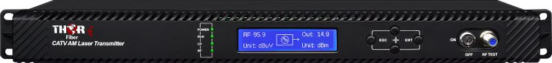
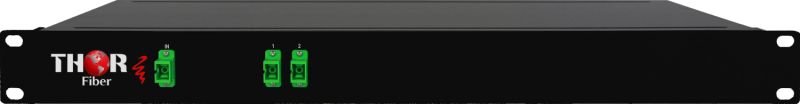
Example signal flow: HDMI sources enter a Thor modulator, the RF output feeds an RF optical transmitter, the fiber is split using PLC splitters, and multiple optical RF receivers convert the signal back to coax for TVs or local RF amplifiers.
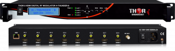
In many systems, the RF source is a multi-channel modulator such as the H-THUNDER-8. It converts HDMI inputs into cable-ready or broadcast-ready RF channels. In other systems, the source may be an antenna feed, an existing cable TV lineup, a MATV system, or a legacy analog RF source.
The transmitter is selected mainly by split ratio, fiber length, connector count, and the amount of engineering margin you want to keep. Larger splits and longer distances require more optical power.
Estimated received optical power = TX output (dBm) − splitter loss (dB) − fiber loss (dB) − connector / patch loss (dB)
For planning purposes, engineers often estimate:
A practical design should not run right at the edge. Leave margin for patch panels, connector contamination, future changes, seasonal drift, and installation variation. A comfortable engineering margin is often 2 to 3 dB.
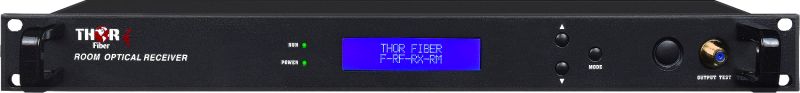
At the far end, the optical receiver converts the light back into RF on coax. From there, the signal can go directly to TVs, into a local RF amplifier, or into a small in-building coax distribution network.
| Small | Point-to-point / 1x8 |
| Medium | 1x16 / 1x32 |
| Large | 1x32 / 1x64 |
A hotel wants to distribute eight in-house channels to several buildings. The headend uses an H-THUNDER-8 to create RF channels from HDMI sources. The RF output feeds an 8mW RF over Fiber transmitter, then a 1x8 F-PLC splitter, and finally one F-RF-RX-RM receiver per building or closet.
This design is attractive because one RF source can feed many endpoints while keeping the familiar coax RF format at the far end.
A university needs RF service across multiple dorms and common areas. A central modulator stack feeds a 16mW transmitter. The optical signal is split through 1x32 PLC splitting and received by rack optical receivers in each building. This avoids very long coax trunks and keeps RF levels consistent across campus.
A large venue or residential development needs one-to-many RF distribution over a wide fiber footprint. Here, a 32mW transmitter is typically the better fit, especially when the optical path includes more distance, more connectors, and large split ratios such as 1x64.
This quick estimator helps customers choose between 8mW, 16mW, and 32mW transmitters. It uses planning values, so it is best used for preliminary design.
Yes. These systems are commonly used for analog NTSC / PAL, digital QAM / J.83B, ATSC 1.0, ATSC 3.0, and antenna RF feeds within the supported band.
As a rule of thumb, 8mW is often suitable for point-to-point and smaller 1x8 layouts, 16mW is often a better fit for larger splitter designs such as 1x16 or 1x32, and 32mW is usually preferred when building high-split or longer-distance networks such as 1x32 and 1x64.
Yes. A modulator can create the RF lineup, and the optical transmitter plus PLC splitter network can carry that lineup to many remote receivers.
No special fiber TV is needed. The optical receiver converts the signal back to standard RF on coax, so the remote side behaves like a normal RF distribution system.
Thor’s transmitter page specifically notes the importance of using SC/APC to reduce reflections in these CATV RF optical links.

 ES
ES

