1x2 Splitter F-PLC-1x2
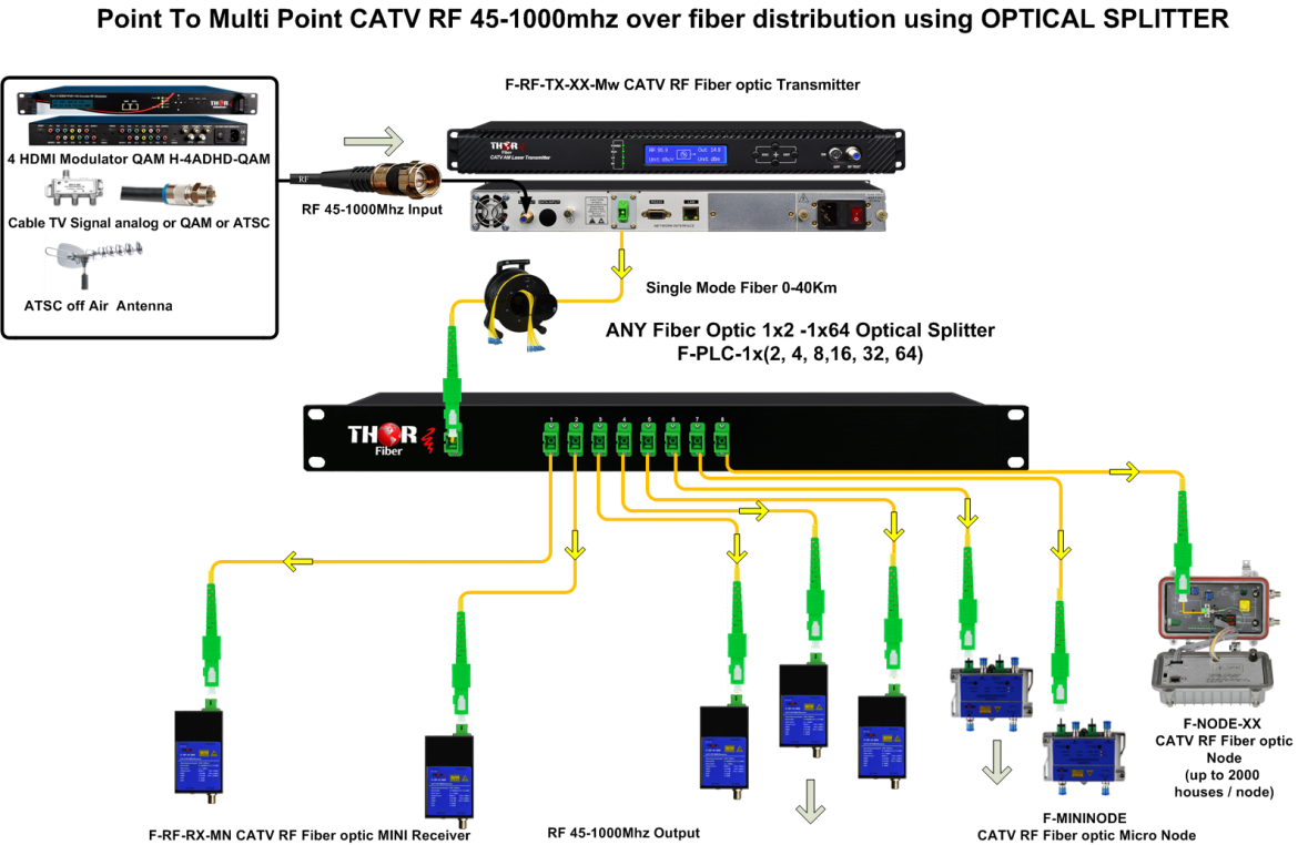
The fiber optical splitter is a passive optical device that can split, or separate, an incident light beam into several light beams at a certain ratio
1x2, 1x4, 1x8, 1x16,1x32,1x64 1U rack mount type PLC splitter and
2x2, 2x4, 2x8, 2x16, 2x32, 2x64 1U rack mount type PLC splitters.
There are four types of fiber optic connectors are widely used for terminating single fibers. They are LC, SC, ST and FC connectors. LC connector has a 1.25mm ceramic ferrule which is only half the size of other connectors. It’s a snap-in connector usually used for high-density applications. SC connector uses a 2.5mm ceramic ferrule and also features a snap-in connection for quick cable patching. Different from other connectors, ST connector uses a bayonet twist-lock connection with 2.5mm ferrule. Moreover, FC is a screw type connector with 2.5mm ferrule but is becoming less popular than LC and SC connectors. This fiber optic splitter/fiber coupler provides Highest Quality Signal
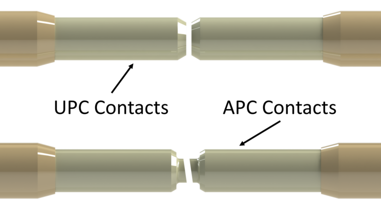
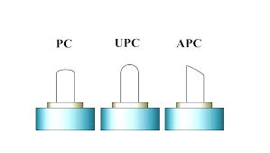
When terminating the optic fiber with connector, you should also decide the polish type if the connector is not polished in advance. Generally, connector end face will be polished to minimize back reflection of light. Using the mated polish styles, light can propagate through connectors with lower fiber loss. There are four types of polish styles – flat, PC, UPC and APC polishes. Among them, UPC and APC types are more popular in the industry. The major difference between UPC and APC connectors is that the APC type is polished at an 8-degree angle while UPC has no angle, but they are both slightly curved for better core alignment. As for the color, UPC connector is usually blue and APC connector is green. Our Fiber Splitter provides Highest Quality Data transfer available.
Please note, each 1x N Optical Splitter Coupler has its own specific INSERTION LOSS
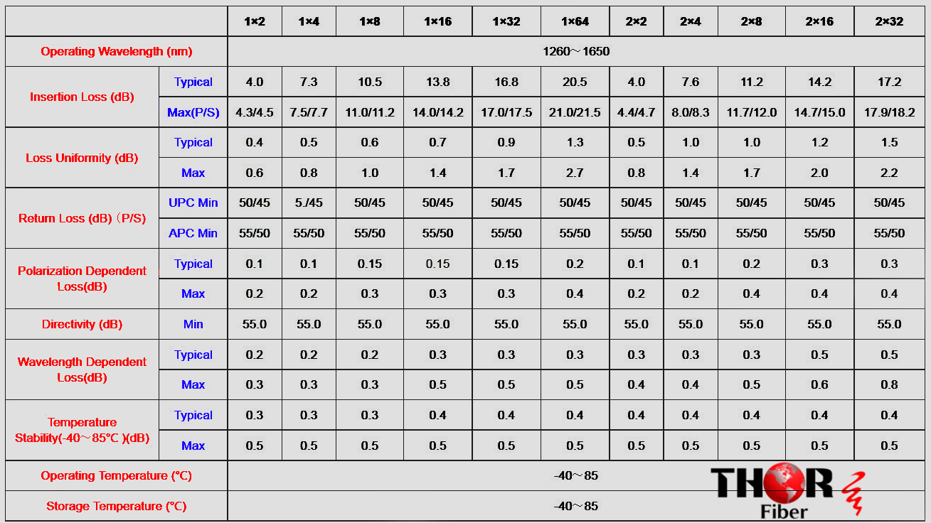
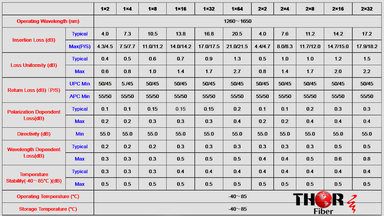
It is the loss of signal power resulting from the insertion of a device in a transmission line or optical fiber and is usually expressed in decibels (dB). The loss table below describes how it works with each box type of signal loss.
1x2 Splitter F-PLC-1x2
1x4 Splitter F-PLC-1x4
1x8 Splitter F-PLC-1x8
1x16 Splitter F-PLC-1x16
1x32 Splitter F-PLC-1x32
1x64 Splitter F-PLC-1x64
INSERTION LOSS 4dB
7.3dB
10.5dB
13.8dB
16.8dB
20.5dB
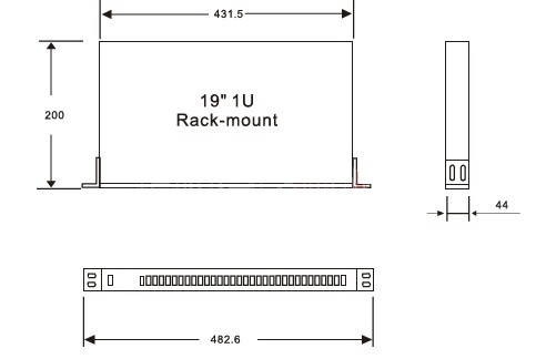
F-PLC-1X2 is a 1x2 optical splitter optical coupler SC/APC connectors. 19" Rack Mountable.
The Insertion loss is 4db
Other connectors type are available per request.
1x2 Rackmount Fiber Optic - Optical Couplers Insertion loss 4dB |
F-PLC-1x2 | |
1x2 Compact LGX Fiber Optic -Optical Couplers Insertion loss 4dB |
F-PLC-1x2-LGX | |
1x4 Rackmount Fiber Optic -Optical Couplers Insertion loss 7.4dB |
F-PLC-1x4 | |
1x4 Compact LGX Fiber Optic -Optical Couplers Insertion loss 7.4dB |
F-PLC-1x4-LGX | |
1x8 Rackmount Fiber Optic -Optical Couplers Insertion loss 10.5dB |
F-PLC-1x8 | |
1x16 Rackmount Fiber Optic -Optical Couplers Insertion loss 13.8dB |
F-PLC-1x16 | |
1x32 Rackmount Fiber Optic -Optical Couplers Insertion loss 16.7dB |
F-PLC-1x32 |
XX : SC/PC, SC/APC, ST/PC, ST/APC, LC/PC, LC/APC, FC/PC, FC/APC
F-PLC Compact LGX
|
Hello
|
|
|
I have some questions about some products
|
I need to know if you can advise me with the correct equipment
|
|
I need to transport an RF signal to two locations from a digital headend to inject the RF signal to an EDFA and distribute it with a Gpon network.
|
The first town is 15 km from the digital head and the second 25 km |
I have planned to use your F-RF-1310-TX with a Fiber Optic Couplers and terminate at the distant site with an F-RF-RX-RM
|
okay
|
what's the amount of splitter do you need?
|
1x8
|
if it is just 1x2 to go to two different towns; it would actually be better to just purchase to separate transmitters 32mW each
|
with distances like 15km and 25km it would also better to get an optical OTDR reading and measure the loss in the fiber lines first
|
the images of your product show distances of up to 40Km
|
how much power is attenuated when using a 1x8 splitter
|
This is based on regular loss of "perfect" conditions. If you are leasing the single-mode fiber, or if it has some loss, distortion, or bends then the optical reading with OTDR will be quite different. You should not depend on a product without knowing what the fiber itself is doing.
|
chart is at the bottom of the webpage for splitters
|
I get it
|
actually there are not only two sites, there are several but right now I need to transport the signal to two sites
|
so if you use a 32mW OTX plus a 1x8 coupler you have about a 5db budget to zero; our receiver will compensate maybe another 10 db; so maybe you will have 15 db to play with but with 25km of fiber that might not be enough.
|
So if you do have use an EDFA, it will be much more expensive but will be your only option. This is why the OTDR reading of the optical fiber is so important; the project can be accomplished on the cheaper side, or could become very expensive.
|
ok
|
I think I should reach my "edfa" with 15db and then distribute with my GPON network
|
I think I should reach my "edfa" with 15db and then distribute with my GPON network
|
What would be the prices of the equipment that you suggest?
|
what is the distance you need to cover with the 1550mw OTx
|
we only make those in 8mW
|
25 km
|
Get an OTDR reading because 8mW on 1550 dissipates at .25db per km
|
ok
|
Insertion loss in passive optical splitters refers to the loss of power that occurs when light is split and distributed to multiple fibers. The term "insertion loss" is used to describe the power loss that occurs as light passes through an optical splitter. The insertion loss is usually measured in decibels (dB) and represents the ratio of the input power to the output power.
Insertion loss in passive optical splitters is caused by several factors, including the imperfections in the splitter's design, the difference in the refractive index of the materials used in the splitter, and the absorption of light by impurities in the splitter.
The most common types of passive optical splitters are the fused biconic taper (FBT) splitter and the planar lightwave circuit (PLC) splitter. FBT splitters are made by fusing two optical fibers together, while PLC splitters are made using micro-optics technology. Both types of splitters have their own unique insertion loss characteristics.
The insertion loss of the FBT splitter is typically higher than that of the PLC splitter, due to the fact that FBT splitters are made by fusing two optical fibers together, which can cause light to be lost due to imperfections in the splicing technique. On the other hand, PLC splitters are made using micro-optics technology, which reduces the insertion loss by allowing for more precise control of the light distribution.
Thor Fiber offers PLC splitters only F-PLC-1x2 - 1x128
The use of passive optical splitters results in each splitter having its own insertion loss. For example, the F-PLC-1x2 1x2 splitter has a 4.5dB insertion loss.
( please chek the insertion loss colum for each type of the splitter )
In summary, insertion loss in passive optical splitters refers to the loss of power that occurs when light is split and distributed to multiple fibers. This loss is caused by several factors such as imperfections in the splitter's design, the difference in the refractive index of the materials used and the absorption of light by impurities. The insertion loss of the FBT splitter is typically higher than that of the PLC splitter.