| Availability: | Check availability | Condition: | new |
|
| Shipping: | starting at $0.00 | Warranty: | 2Yrs |
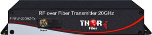
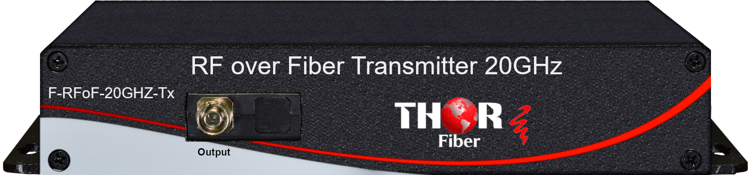
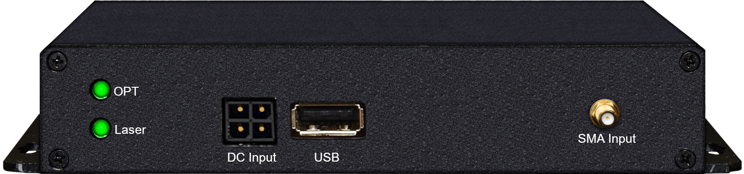
The Thor 20GHz Transmitter F-RFoF-20GHZ-TX is a high-performance Lightwave Transmitter Module designed for analog photonics applications from DC to 20 GHz. This unit includes an 18 GHz optical intensity modulator and an Automatic Bias Control (ABC) board with four different operating modes. The external laser source can be any polarization-maintaining device, such as tunable laser, narrow linewidth laser, making it a versatile solution for RFoF system integration. Contact Optilab for more information.
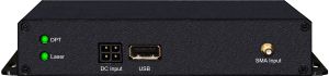
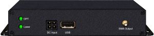
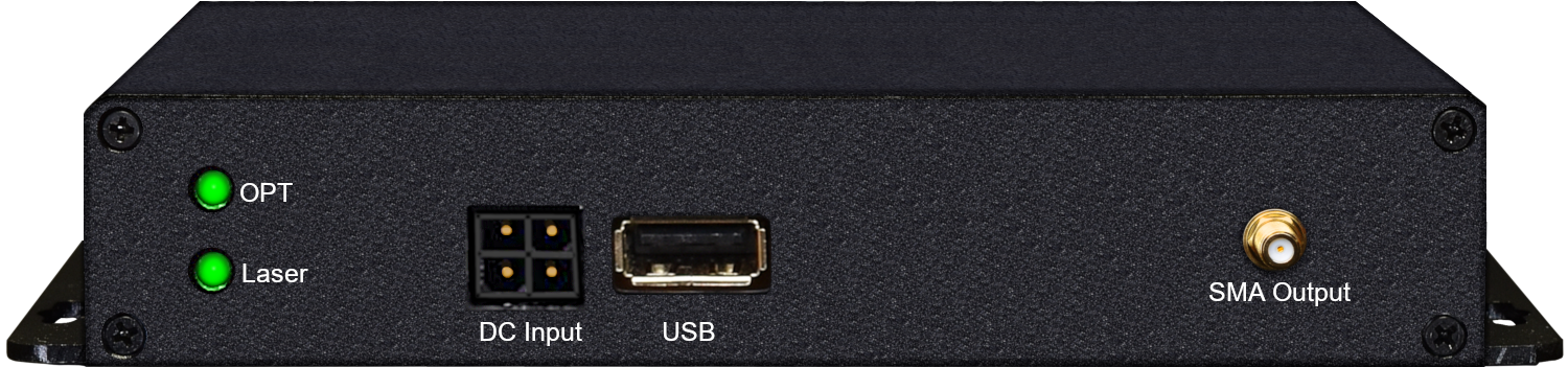
The F-RFoF-20GHZ-RX is a 20 GHz photodiode module designed for RF over Fiber, antenna remoting, and broadband RF transmission applications using single mode optical. The F-RFoF-20GHZ-RX can accept input power of up to 35 mW. The F-RFoF-20GHZ-RX utilizes a high input power, low distortion PIN photodiode that provides optical to RF conversion out to the frequency range beyond 20 GHz. This compact, cost-effective receiver module can provide users with status monitoring through the use of an on-board processor that communicates to a host computer over an RS-232 I/O interface via a standard USB 2.0 port. When the F-RFoF-20GHZ-RX RF over fiber receiver module is linked with the TX series of RF over fiber transmitter modules, the combination provides an excellent solution for ultra-wideband RF to fiber conversion applications, go to optilab.com for more details
Features:
Customizable options:
Applications:
Features:
Applications:
F-RFoF-20GHZ-TxRx 20Ghz over fiber -Transmitter / Receiver kit
|
General Specifications |
|
|
Operating Wavelength |
1520 nm to 1610 nm |
|
Laser Source |
Internal DFB laser, 1550nm+/-10 nm; other wavelength and narrow linewidth <1 MHz are available |
|
Laser Power Level |
20 mW, 30 mW, 40 mW, 50 mW |
|
RF Return Loss |
>15 dB @ 10 GHz; >10 dB @ 20 GHz |
|
Impedance |
50 Ohm |
|
Operating Frequency Range |
DC to 25 GHz |
|
Input RF Voltage |
27 dBm max. |
|
Optical Output Level |
6.5 dBm typ. with 20 mW DFB |
|
S21 Bandwidth |
3 dB, 2 GHz to 18 GHz typ. |
|
Modulator Bias Mode |
4 Automatic bias control modes, selectable by software |
|
Extinction Ratio |
25 dB typ.; >30 dB (HE version) |
|
Modulator Voltage Vp |
7 V typ. @10 GHz; 5.5 V typ. @ 10 GHz (LD version) |
|
Analog Link Performance |
|
|
MP3 @7 GHz |
32 dBm typ.; 29 dBm typ. (LD version) |
|
1 dB Compression Point @10 GHz |
|
|
Mechanical Specifications |
|
|
Operating Temperature (standard) |
-30 deg C to +60 deg C |
|
Operating Temperature (TQ version) |
-55 deg C to +75 deg C |
|
Storage Temperature |
-60 deg C to +90 deg C |
|
Power Supply Requirements |
+/-5V, 1A typ. |
|
Optical Connectors |
FC/APC |
|
Fiber Type |
SMF-28 output; PANDA output (PM version) |
|
RF Input Connector |
K connector |
|
Power Connector |
4 Pin Molex |
|
Remote Control |
USB 2.0 software included |
|
Alarm |
LED bias mode status |
|
Dimensions |
206 mm x 102.4 mm x 31.5 mm |
Mode |
Operation Conditions |
|
Q+ |
Set to quadrature point of positive slope for linear analog modulation |
|
Q- |
Set to quadrature point of negative slope for linear analog modulation |
|
Min |
Set to min. point of operation for the pulse generator or digital modulation |
|
Max |
Set to the max. point of operation for pulse generator or digital modulation |
|
General Specifications |
|
|
Photodiode Wavelength Range |
1260 nm to 1600 nm |
|
Operational Bandwidth |
60 KHz to 20 GHz |
|
Optical Input Level |
35 mW max. |
|
Responsitivity |
0.85A/W @ 1550nm typ. 0.90A/W @ 1310nm typ. 0.40A/W @ 850nm typ. |
|
S21 3 dB Bandwidth |
17 GHz min., 19 GHz typ. |
|
S22 Characteristics |
< -10 dB @ 20 GHz |
|
Optical Return Loss |
-30.0 dB typ. |
|
2nd Harmonics Distortion |
-70.0 dBc max. |
|
3rd Harmonics Distortion |
-75.0 dBc max. |
|
Optical POL @ 1550 nm |
0.05 dB max. |
|
Output Coupling |
AC Coupled |
|
RF impedance |
50 Ohm |
|
Ripple over Bandwidth |
+/-1.0 dB max. |
|
Link Performance |
|
|
SFDR |
113 dB Hz 2/3 |
|
Link Loss |
- 20 dB @ 10 dBm optical |
|
Mechanical Specifications |
|
|
Operating Temperature |
-10 deg C to +50 deg C |
|
Storage Temperature |
-20 deg C to +80 deg C |
|
Power Supply Requirements |
+5 V DC,500 mA max. |
|
Optical Connector |
FC/APC, SC/APC Optional |
|
RF Input Connector |
K Connector Female, 50 Ohm |
|
DC Connector |
Plug-in typ. |
|
Local Alarm |
LED: Optional Input Power |
|
Remote Alarms |
RS-232 Interface (Standard) via USB |
|
Dimensions |
82mm x 56mm x 25mm |
|
Accessories Included |
110V - 240V AC USB Adaptor & Cable |
|
Housing |
Precision Machined Anodized Aluminum |
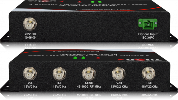 4 x Satellite L-Band LNB's + 1 CATV QAM / ATSC RF over 1 fiber Transmitter F-SattGalaxy-TXRX-5 MDU Distribusion Solution
Thor Fiber MDU Satellite over Fiber - Optical Transmitter F-SattGalaxy-TX-5 has 5 independent RF inputs, converts each satellite signal from a quad or quattro LNB, and also a terrestrial off-air TV signal via an antenna array in a single unit for transmission over one singlemode fiber. Thor Optical MDU Satellite Receiver F-SattGalaxy-RX converts the optical signal back to the original 4 satellite signals and the fifth terrestrial off-air TV signal injected into the TX. Off-air TV / Radio signals such as ATSC, analog NTSC, DVB-T, ISDB-T, DVB-C QAM Annex A/B, or RF FM Radio can be used in the 5th RF port for transmission.
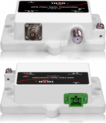 1 GPS Fiber Transport System
Single GPS fiber extender up to 20Km over single-mode fiber with SC/APC connectors
 ES
ES


