| Availability: | Check availability | Condition: | new |
|
| Shipping: | starting at $0.00 | Warranty: | 2Yrs |
Part Number F-GPS-TX-WE / F-GPS-TX-RM
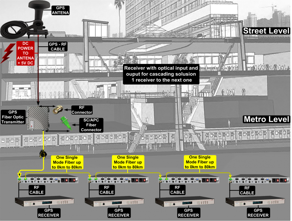
The Thor Fiber GPS over Fiber outdoor weather kit allows you to send a GPS signal over long distances for synchronizing cellular base stations.
Allows transmission of all the main signals in the GPS band: L1, L2, L3, L4, L5, L6, L7.
By using a built-in LNA, this GPS over Fiber link is designed to offer a very low noise figure.
Sending GPS over coax is very difficult over long distances, so our GPS system has many different advantages:
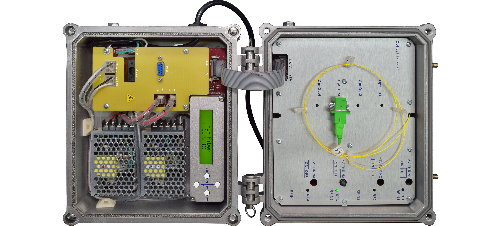
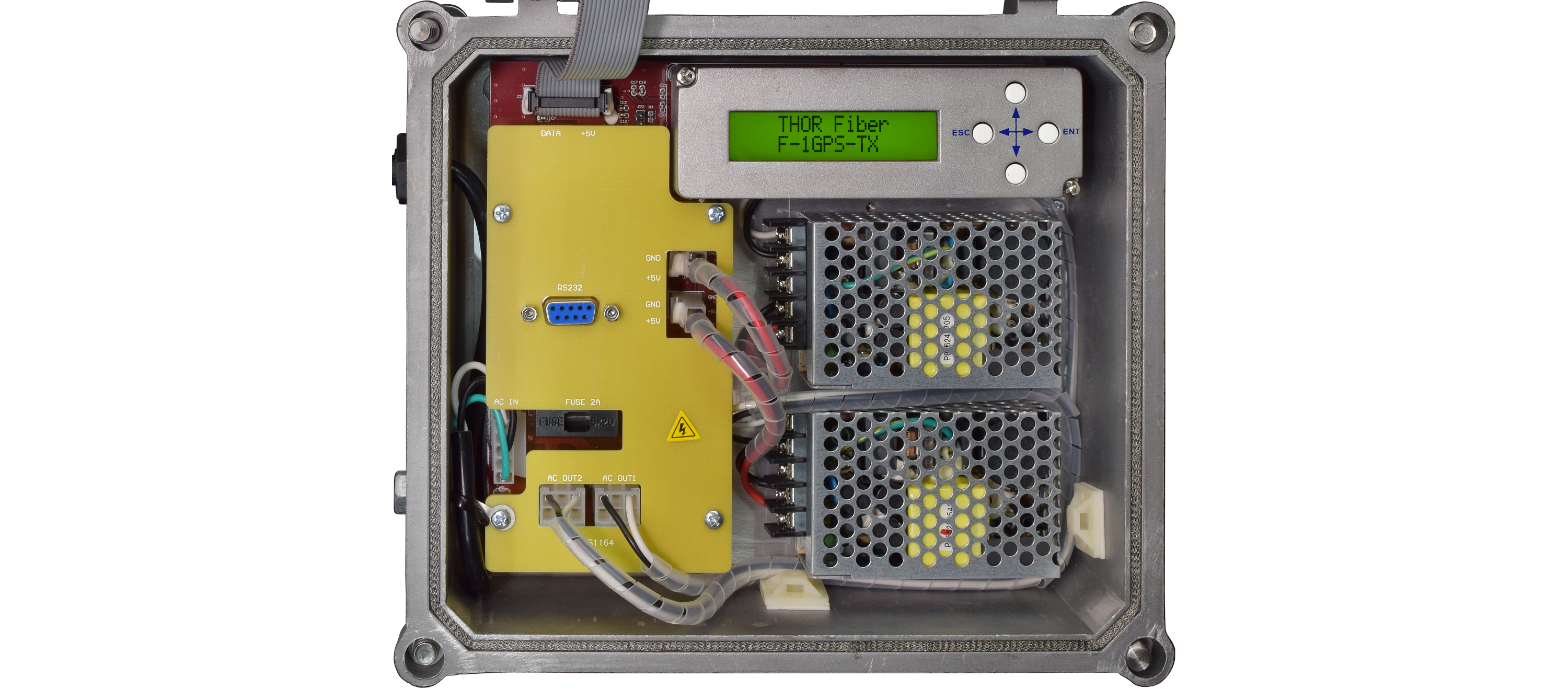
Units have LCD displays to show RF and optical levels that are built into our units.
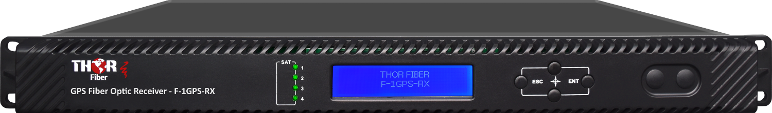
The transmitter shows incoming RF level and optical output power. The receiver has a built-in optical power meter and RF output level meter, allowing simple troubleshooting.
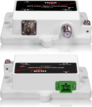
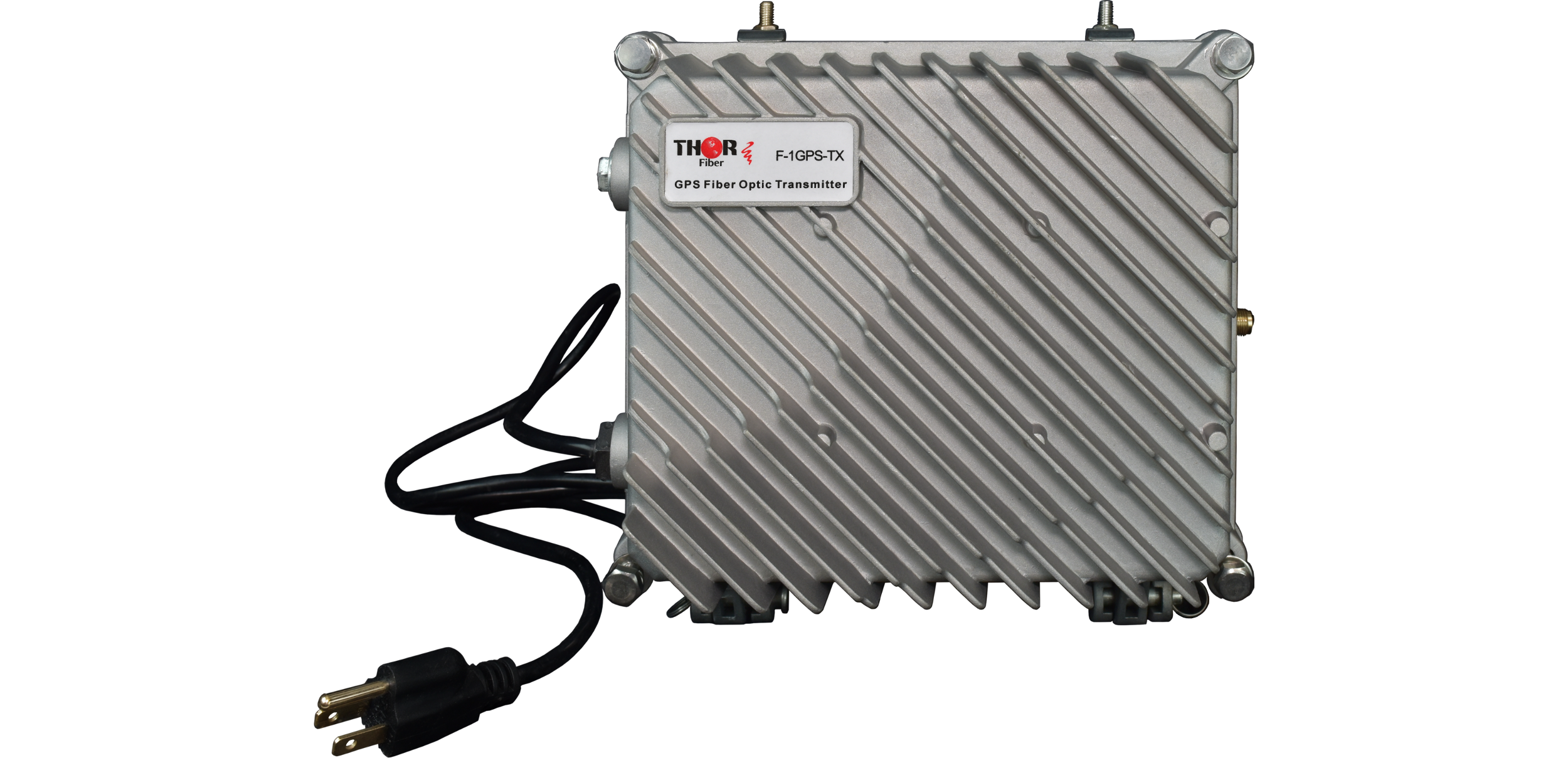
The transmitter is waterproof, and the receiver is rack-mountable in a 1RU chassis.
The transmitter has Bias-T and can power an active GPS antenna.
Both transmitter and receiver have dual redundant power supplies, making them very robust and pragmatic for commercial architectures.
These systems are very easy to deploy and can offer various configurations for many applications.
The main receiver is 19' rack-mountable, but the transmitter has a built-in compact enclosure that is deployable in any environment.
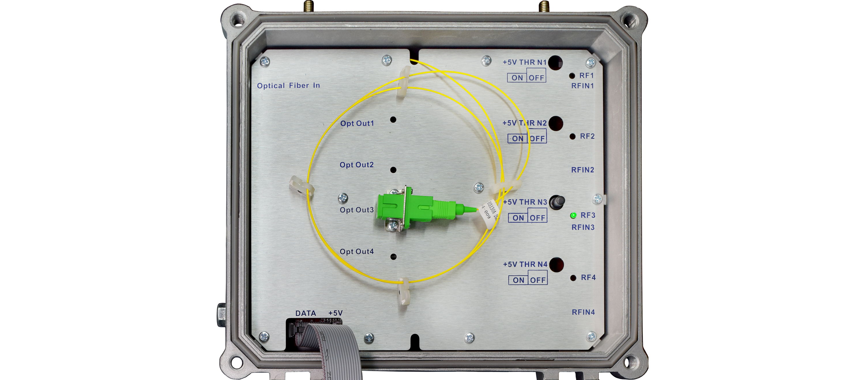
Units are used as a point-to-point transmission from the transmitter to the receiver, but the transmitter can be accompanied by our optical splitters, which can be used for point-to-multipoint applications (star configuration) 1x2, 1x4, 1x8, 1x16 and 1x32.
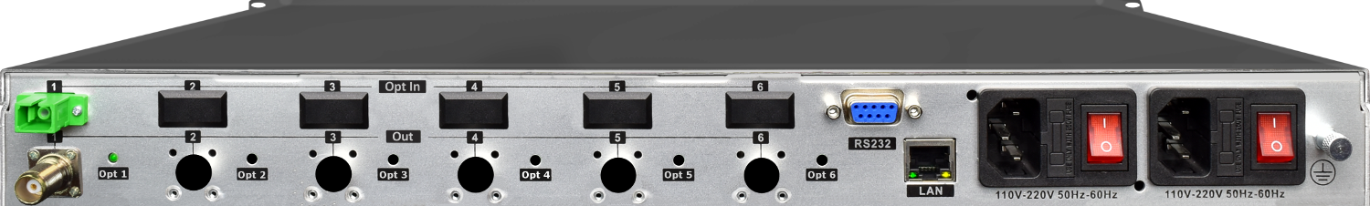
It's also possible to add additional splitters on the receiver side and have up to 6 GPS outputs on the receiver (special order).
You can add 1x2 optical splitters to the receiver and use them as in-line from one receiver to the next in a cascading configuration for easy distribution.
Our GPS equipment is designed to support a wide range of GPS signals, ensuring maximum performance, accuracy, and flexibility across different applications. The equipment is compatible with the latest modernized GPS signals, enabling enhanced precision, robustness, and reliability for both civilian and military use. Below is a list of the GPS L bands and their corresponding frequencies that our equipment supports:
L1 - 1575.42 MHz
Civilian (C/A code), Military (P(Y) code)
L2 - 1227.60 MHz
Military (P(Y) code), Civilian (L2C code)
L3 - 1381.05 MHz
Nuclear Detonation Detection (Not used for navigation)
L4 - 1379.913 MHz
Ionospheric Research (Limited Use)
L5 - 1176.45 MHz
Civilian Safety-of-Life (Aviation)
L6 - 1278.75 MHz
Commercial Use (GPS III)
L7 - 1267.6 MHz
Modernized GPS III Signal
This comprehensive support ensures our equipment can deliver accurate positioning and navigation in diverse environments and scenarios, from basic navigation tasks to advanced, high-precision applications.
GPS-over-Fiber Applications:
IMPORTANT NOTE*** (It is very important to interface our unit with SC/APC - Angle Polished Connector to avoid any light reflections.)
If your fiber is terminated with the SC, ST, FC /PC flat connector, you need to use an optical jumper from PC type to SC/APC for proper conversion.
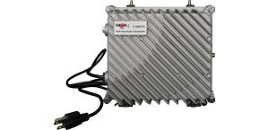
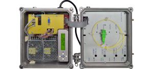
Transmitter -Weatherproof Enclosures NEMA 4 and dual power supply, LCD display, RF and Optical meters built in
F-GPS-TX-WE - GPS fiber optic Transmitter
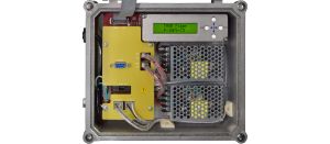
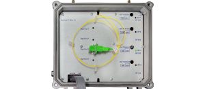
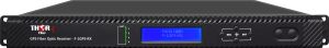
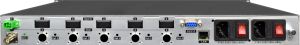
Receiver -19" rack mountable enclosure ,LCD display, RF and Optical meters and dual power supply
F-GPS-RX-RM GPS fiber optic Receiver (one RF GPS output)
F-GPS-RX-RM-XX (XX = 2-6) GPS fiber optic Receiver (2 - 6 RF GPS outputs)
F-GPS-RX-RM-OU GPS fiber optic Receiver with Optical Output for cascading
IMPORTANT NOTE*** (It is very important to interface our unit with SC/APC - Angle Polished Connector to avoid any light reflections.)
If your fiber is terminated with the SC, ST, FC /PC flat connector, you need to use an optical jumper from PC type to SC/APC for proper conversion.
GPS FIBER TRANSMITTER
| Item | Unit | Indexes | Remark |
|
Optical Characteristics |
|||
|
Laser Type |
DFB | ||
| Optical Wavelength | nm | 1310 or (CWDM 1510,1530,1550,1570nm -Special order) |
Specified by the user |
|
Optical Output Power |
mW | 1 or (2,3,4,8 -Special order) |
Specified by the user |
|
Optical Return Loss |
dB | 50 | |
|
Optical Connector Type |
SC/APC |
Specified by the user |
|
|
RF Characteristics |
|||
|
Input Impedance |
Ohm | 50 | |
|
RF Connector |
N type by default or TNC type by request |
Specified by the user |
|
|
Operating Bandwidth |
MHz | 85~2400 | |
|
Input Range |
dBuV | 47~67 |
Input level (AGC attenuation=0) |
|
Flatness |
dB | +/-2 |
50~600MHz |
|
+/-2 |
600~2000MHz |
||
|
Input Return Loss |
dB | 12 |
50~2400MHz |
|
C/IM3 |
>=55 |
Note 1 |
|
|
AGC attenuation |
dB | -7~+7 |
Note 2 |
| Frequency Response (85-2400MHz) | dB | +/-1.2 | |
| Input Noise Floor @1GHz |
dBm/Hz |
-149 _ - 153 | EIN |
| Input Third Order Intercept @1GHz | dBm | 12 | IIp3 |
| RF Link Gain | dB | 20 | |
| Spur Free Dynamic Range | (dB/Hz)2/3 | 109 | SFDR |
| Isolation | dB | 50 - 60 | |
|
General Characteristics |
|||
|
Serial Interface |
RS232 | ||
|
Power Supply (AC) |
V | 100~240 |
Optional dual power |
|
Consumption |
W | 10 | |
|
Relative Humidity |
% | 5~95 | |
|
Working Temperature |
deg C | -20~60 | |
|
Storage Temperature |
deg C | -40~70 | |
|
Dimension (W)*(D)*(H) |
mm | 1U 19 inch 483*395*44 |
|
Note 1: C/IM3 is defined as the ratio between the peak of carrier signal and triple beat (IM3) by using a two-tone test (1.0GHz and 1.1GHz).
Note 2: The test condition adopts the specified optical transmitter, AGC attenuation= 0 and optical receiving power= -5dBm.
GPS FIBER RECEIVER
| Item | Unit | Indexes | Remark |
|
Optical Characteristics |
|||
|
|
|||
|
Optical Wavelength |
nm | 1260-1620 |
|
|
Responsivity |
A/W |
>=0.9 |
|
|
Optical Return Loss Optical Receiving Power |
dB dB |
>= 50 -12 ~0 |
|
|
Optical Connector Type |
SC/APC |
|
|
|
RF Characteristics |
|||
|
Input Impedance |
Ohm | 50 | |
|
RF Connector |
TNC type, N type |
Specified by the user |
|
|
Operating Bandwidth |
MHz | 85~2400 | |
|
Output Impedance |
Ohm | 50 | |
|
Flatness |
dB | +/-2 |
50~600MHz |
|
dB |
+/-1.5 |
600~2000MHz |
|
|
Input Return Loss |
dB | 12 |
50~2400MHz |
|
C/IM3 |
>=55 |
Note 1 |
|
|
AGC attenuation |
dB | -7~+7 |
Note 2 |
| Frequency Response (85-2400MHz) | dB | +/-1.2 | |
| Input Noise Floor @1GHz |
dBm/Hz |
-149 _ - 153 | EIN |
| Input Third Order Intercept @1GHz | dBm | 12 | IIp3 |
| RF Link Gain | dB | 20 | |
| Spur Free Dynamic Range | (dB/Hz)2/3 | 109 | SFDR |
| Isolation | dB | 50 - 60 | |
|
General Characteristics |
|||
|
Serial Interface |
RS232 | ||
|
Power Supply (AC) |
V | 100~240 |
Optional dual power |
|
Consumption |
W | 10 | |
|
Relative Humidity |
% | 5~95 | |
|
Working Temperature |
deg C | -20~60 | |
|
Storage Temperature |
deg C | -40~70 | |
|
Dimension (W)*(D)*(H) |
mm | 1U 19 inch |
483*395*44 |
Note 1: C/IM3 is defined as the ratio between the peak of carrier signal and triple beat (IM3) by using a two-tone test (1.0GHz and 1.1GHz).
Note 2: The input level range is 47~67dBuV when AGC attenuation=0; the input level range is 48~68dBuV when AGC attenuation=1. That is to say, if AGC attenuation increases by 1dB, the input level will correspondingly increase by 1dB and the optical receiver output level will also increase by 1dB (with the same optical power received). The reduction rule is just the same.
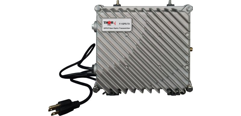
Our GPS over fiber optic transmitter and receiver, F-1GPS-TX/RX, or Lband F-LBAND-TX/RX, support frequencies ranging from 54-2600 MHz. It is protocol-independent, so it does not measure the modulation in use but rather the band spectrum.
After conducting some research, I found that the MUOS system uses a narrowband waveform operating at a frequency of 300-320 MHz and a wideband waveform operating at a frequency of 1200-1300 MHz.
The narrowband waveform offers voice and low data rate communications, while the wideband waveform offers high data rate communications for video and large file transfers. Therefore, our GPS over fiber optic transmitter and receiver should work with the MUOS system.
F-1GPS-TX/RX
Another thing that needs to be checked is the RF power. Our RF transmitter requires an input of 10-25 dBmV, with the same corresponding output on the receiver.
Since the MUOS system is bi-directional, you would need to use two sets of the TX/RXs and use them in reverse over 2 fibers. Most likely, you would need to use a circulator or duplexer between TX and RX to avoid a signal loop.
In summary, the devices should work if the RF frequency and RF power are in range.
The MUOS waveform is a satellite communications waveform developed for use by the United States Department of Defense's (DoD) Mobile User Objective System (MUOS). The MUOS waveform provides advanced voice, data, and video communications capabilities to mobile and tactical users worldwide. It is designed to provide enhanced communication capabilities to military users in remote or difficult-to-reach locations, such as ships, aircraft, and land-based vehicles. The waveform is designed to operate in multiple frequency bands and offer features such as anti-jamming, low probability of detection, and enhanced security.
The MUOS (Mobile User Objective System) waveform operates in the Ultra High Frequency (UHF) band, specifically in the range of 300 MHz to 3 GHz. The MUOS system uses five geostationary satellites to provide global coverage.
The MUOS system has a narrowband waveform that operates at a frequency of 300-320 MHz and a wideband waveform that operates at a frequency of 1200-1300 MHz. The narrowband waveform offers voice and low data rate communications, while the wideband waveform offers high data rate communications for video and large file transfers.
The MUOS system uses a frequency division multiple access (FDMA) technique, which allows multiple users to share the same frequency band by dividing the band into smaller sub-channels. This helps to increase the efficiency of the system and reduce interference between users.
It is bi-directional, meaning that it supports two-way communication. This allows users to not only receive information but also to transmit information back to the network. The bi-directional capability is essential for military operations as it enables troops to communicate and exchange information in real time, which is critical for mission success.
The MUOS (Mobile User Objective System) waveform uses a 50-ohm impedance antenna. This is the standard impedance used for most UHF communications systems, including military and commercial systems. A 50-ohm impedance is commonly used because it provides an optimal match between the antenna and the transmitter or receiver, minimizing signal reflections and maximizing signal efficiency. The use of a 50-ohm impedance antenna helps to ensure that the MUOS system can operate efficiently and effectively, providing reliable communications for military users in remote or difficult-to-reach locations.
We have the perfect solution for GPS over fiber extenders. Below are the available options:
https://thorbroadcast.com/product/1-gps-fiber-transport-system.html
We also offer optical splitters:
https://thorbroadcast.com/product/1-x-2-to-1-x-128-fiber-optic-couplers.html
Please let me know your desired configuration and quantity. Kindly note that these devices require single-mode fiber terminated with SC/APC connectors.
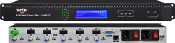 6 Ch L-Band Satellite Over single Fiber Extender Transmitter and Receiver 54-3000Mhz -CWDM
6-channel Satellite LNB fiber-optic Extender. 6 LNB satellite TV antenna feed over fiber-optic transmission system with internal CWDM optics. Ideal for point-to-point transport or for small-scale (Level 1 only) LTTH distribution systems with 32 or fewer optical receivers. Supports ATSC feed from a local off-air antenna, 54-3000mHz. Best satellite distribution system for MDU - Multi-Dwelling Unit
 1 GPS Fiber Transport System
Single GPS fiber extender up to 20Km over single-mode fiber with SC/APC connectors
 ES
ES


