| Availability: | In stock | Condition: | new |
|
| Shipping: | starting at $0.00 | Warranty: | 1Yrs |
The Thor Fiber portable F-1GPS-TX/RX systems are available to support the remote placement of industrial GPS antennas. These kits are assembled and tuned to the unique requirements of each application. Thor GPS over fiber systems are an excellent solution for distance limitations between maritime or government GPS antennas and radio signal receiver equipment. Typically, any sensor equipment or tuning hardware, such as universal time receivers or GPS navigation gear, must be installed and located within 100 ft of the antenna system. Most modern industrial type systems require antennas with a clear view of the horizon to function properly. In the case of large ocean-going vessels, underground military installations, or large buildings or structures (metropolis), it can be a challenge to install GPS equipment within 100 ft of a suitable antenna location. Thor solves this problem by extending the distance to over 20km by converting the GPS signal from the antenna's coax to fiber optic cable. F-GPS systems are available in a variety of form factors, and can be custom tuned to individual users' applications.
GPS reference timing signals are widely used to synchronize cellular base stations.
GPS systems typically consist of an active rooftop antenna, a GPS receiver, and a length of coaxial cable to connect them. Common challenges arise when the distance between the rooftop antenna and the cellular base station equipment (usually in the basement) is greater than 300 ft. Coaxial cable runs over 300 ft are not practical for most GPS receiver systems, so a fiber optic link is required at such distances, and Thor fiber optic links are some of the most trusted and cost-effective links in the industry.
IMPORTANT NOTE*** (It is very important to interface our unit with SC/APC - Angle Polished Connector to avoid any light reflections.)
If your fiber is terminated with the SC, ST, FC /PC flat connector, you need to use an optical jumper from PC type to SC/APC for proper conversion.
The L signals are different frequency bands used by GPS (Global Positioning System) satellites to transmit signals to GPS receivers. These frequencies are part of the evolution of GPS technology, providing higher accuracy, better reliability, and more advanced features, especially with the modernization of GPS.
Here are the key L bands for GPS and their corresponding frequencies:
| Signal | Frequency (MHz) | Description |
|---|---|---|
| L1 | 1575.42 | Civilian (C/A code), Military (P(Y) code) |
| L2 | 1227.60 | Military (P(Y) code), Civilian (L2C code) |
| L3 | 1381.05 | Nuclear Detonation Detection (Not used for navigation) |
| L4 | 1379.913 | Ionospheric Research (Limited Use) |
| L5 | 1176.45 | Civilian Safety-of-Life (Aviation) |
| L6 | 1278.75 | Commercial Use (GPS III) |
| L7 | 1267.6 | Modernized GPS III Signal |
These frequencies ensure that GPS signals can be used effectively in various applications, from consumer navigation to precise scientific and military purposes. The modernized signals like L5, L6, and L7 are designed to offer enhanced performance in terms of accuracy, reliability, and resistance to interference.
F-1GPS-TX/RX - 1GPS over fiber Transmitter/Receiver kit (both ends) - 1mW laser (20km distance)
F-1GPS-TX - 1GPS over fiber Transmitter only - 1mW laser - 0dBm optical output power (20km distance)
F-1GPS-RX - 1GPS over fiber Receiver only
F-1GPS-TX-10mW - 1GPS over fiber Transmitter only - 10mW laser +10dBm optical output power
|
*All Specifications Subject to Change Without Notice IMPORTANT NOTE*** (It is very important to interface our unit with SC/APC - Angle Polished Connector to avoid any light reflections.) If your fiber is terminated with the SC, ST, FC /PC flat connector, you need to use an optical jumper from PC type to SC/APC for proper conversion. |
|||
|
Electro Optical Characteristics |
|
||
|
1 mW min. (F-1GPS-TX - 1GPS over fiber Transmitter only - 1mW laser - 0dBm optical output power (20km distance) (0-+3)dBm -10dBm 10 dB (*** F-1GPS-TX-10mW - 1GPS over fiber Transmitter only - 10mW laser +10dBm optical output power) |
||
|
1310 nm (1550 nm or CWDM special order only) |
||
|
RF Characteristics |
|
||
|
1100 - 1585.42 MHz |
||
|
60 dB |
||
|
2.0:1 max |
||
|
0.1 mW/ma min |
||
|
-25 dBm |
||
|
12VDC, 1.5A AC to DC power supply - Included (F-Type Female) 5V DV (ON/OFF switch) |
||
|
Physical Characteristics |
|
||
|
Height 1 1/16" Width: 4 1/32" (with RF and Fiber connectors) Length: 4" |
||
|
Link Characteristics |
|
||
|
15 dB typical |
||
|
15 dB min with input drive level at 70 dBm |
||
|
22 dBm |
||
|
Environmental Conditions |
|
||
|
-25 to +70 (deg C) |
||
|
-30 to +75 (deg C) |
||
|
Mechanical |
|
||
|
SC/APC Fiber S/M 9/125 N type Female |
||
There is no reason why it shouldn't; our units are wideband and totally transparent.
GPS (Global Positioning System) is a satellite-based navigation system that allows users to determine their precise location, speed, and time anywhere on Earth. GPS signals are transmitted from a network of satellites orbiting the Earth and can be received by GPS receivers on the ground or in aircraft, ships, and other vehicles.
GPS frequencies are within the L-band range of the radio frequency spectrum, specifically within the 1575.42 MHz frequency band. These signals are very weak, with an average power of just -160 dBm (decibel-milliwatts), and are susceptible to interference and signal loss over long distances.
To send GPS signals over fiber optic cables, a GPS modulator and a fiber optic transmitter are used. The GPS modulator converts the GPS signals into a format that can be transmitted over fiber optic cables, while the fiber optic transmitter sends the signals over the fiber optic cables to the desired location.
There are several types of fiber optic transmitters that can be used to send GPS signals over fiber, including both analog and digital transmitters. The choice of transmitter will depend on the specific requirements of the application, including the distance the signal needs to be transmitted, the type of fiber optic cable being used, and the data rate of the signal.
It is also important to note that GPS signals are susceptible to interference and signal loss over long distances, so it may be necessary to use amplifiers or repeaters to boost the signal along the way. This is particularly important when transmitting GPS signals over long distances, as the signals can become degraded due to factors such as atmospheric conditions and other sources of interference.
In addition to being used for navigation and location-based services, GPS signals are also used in a wide range of applications, including surveying, mapping, timing, and scientific research. The ability to transmit GPS signals over fiber optic cables enables a wide range of possibilities for these applications, including the ability to transmit GPS signals to remote locations that may not be accessible by other means.
Fiber optic cables are a reliable and efficient means of transmitting GPS signals over long distances. They offer several advantages over traditional copper cables, including higher bandwidth, higher data rates, and immunity to electromagnetic interference. They are also more resistant to physical damage and are less susceptible to corrosion.
To transmit GPS signals over fiber optic cables, the signals must be converted into a format that is compatible with fiber optic transmission. This is typically done using a GPS modulator, which converts the GPS signals into an optical format that can be transmitted over fiber optic cables.
There are several types of GPS modulators available, including both analog and digital modulators. Analog modulators use continuous wave (CW) lasers to transmit the GPS signals, while digital modulators use pulse-code modulation (PCM) to transmit the signals in digital form. The choice of modulator will depend on the specific requirements of the application, including the distance the signal needs to be transmitted and the data rate of the signal.
Once the GPS signals have been modulated, they can be transmitted over fiber optic cables using a fiber optic transmitter. There are several types of fiber optic transmitters available, including both analog and digital transmitters. The choice of transmitter will depend on the specific requirements of the application, including the distance the signal needs to be transmitted, the type of fiber optic cable being used, and the data rate of the signal.
It is also important to note that GPS signals are susceptible to interference and signal loss over long distances, so it may be necessary to use amplifiers or repeaters to boost the signal along the way. This is particularly important when transmitting GPS signals over long distances, as the signals can become degraded due to factors such as
Based on the antenna specifications, it looks like it should work because we are directly modulating incoming RF signals into an optical wavelength output. It should be quick and easy to set up. Just make sure you have single-mode fiber and SC/APC connectors.

Note on Equipment Supporting All GPS L Bands
Our GPS equipment is designed to support a wide range of GPS signals, ensuring maximum performance, accuracy, and flexibility across different applications. The equipment is compatible with the latest modernized GPS signals, enabling enhanced precision, robustness, and reliability for both civilian and military use. Below is a list of the GPS L bands and their corresponding frequencies that our equipment supports:
Supported GPS L Bands and Frequencies:L1 - 1575.42 MHz Civilian (C/A code), Military (P(Y) code)
L2 - 1227.60 MHz Military (P(Y) code), Civilian (L2C code)
L3 - 1381.05 MHz Nuclear Detonation Detection (not used for navigation)
L4 - 1379.913 MHz Ionospheric Research (limited use)
L5 - 1176.45 MHz Civilian Safety-of-Life (Aviation)
L6 - 1278.75 MHz Commercial Use (GPS III)
L7 - 1267.6 MHz Modernized GPS III Signal
Yes, the fiber optic coupler shown (F-PLC-1x4) is a passive device.
Our standard 1 mW TX can be split up to 4 times. We also offer a 10 mW TX that can be split up to 16 times, depending on your setup.
Regarding your question about the GPS OUT port: yes, the RF output has unity gain relative to the RF input from the antenna. It is intended to connect directly to the GPS input of your equipment (not to another antenna).
How many endpoints are you looking to support? If you require multiple endpoints, there are two recommended configurations:
Multiple 1 mW TX units with individual 1x4 splitters - This setup provides redundancy and flexibility.
A single 10 mW TX with a 1x16 optical splitter - This is more centralized and efficient for higher endpoint counts.
Here is the link to the 75Ohm L-Band over Fiber TX/RX kit: https://thorbroadcast.com/product/l-band-over-fiber-tx-rx-basic-1-ch-kit.html
Here is the link to the 50Ohm GPS over Fiber TX/RX kit (both can cover cellular frequencies): https://thorbroadcast.com/product/1-gps-fiber-transport-system.html
However, these are unidirectional transmitter/receiver sets. For cellular applications, you would typically need two sets, along with an RF circulator or (even better) a diplexer.
Hopefully that makes sense - we have had clients use this solution for Cellular over Fiber, and it works great as long as your RF spectrum stays within the supported frequency range.
Here is the connection diagram:

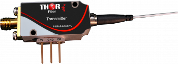 6GHz RF over Fiber
Up to 6GHz analog RF optical transport - RF over fiber Transmitter / Receiver for Satcom, GPS, WiMAX, LTE, and DAS RF transport applications
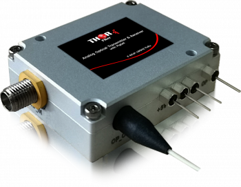 18GHz Ku-Band Fiber Optic Mini Transmiter / Receiver
Analog RF 10MHz to 18GHz Ku-Band fiber optic mini transmitter and receiver set F-RFoF-18GHZ-TxRx
 ES
ES


