| Availability: | In stock | Condition: | new |
|
| Shipping: | starting at $0.00 | Warranty: | 2 Years |
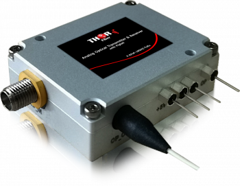
Mini RF over Fiber Transmitter & Receiver kit supporting a frequency range of 100Mhz to 4000Mhz (4Ghz), functioning as a transparent RF fiber link.
Using copper as a medium has significant limitations due to substantial loss, which is why fiber optic RF over Fiber Transmitters and Receivers solve the distance transport problem.
It is used in many RF over fiber applications, such as communications, defense systems, satellite L-band, S-band, GPS, WiMAX, cellular 3G, 4G, and LTE signals.
DAS systems linking the Base Station (BS) to single or multiple Remote Antenna Units (RAU).
The unit has SMA 50ohm electrical interfaces and FC/APC optical interfaces; base mode operates on 1310nm and supports distances of up to 20km over single mode fiber.
These units do NOT support multimode fiber.
Customized units are also available for long-haul distances or optical wavelengths.
Fiber optics provide several other significant network advantages, including simplified network design, ease of installation, and immunity to EMI/RFI and lightning.
Applications
IMPORTANT NOTE*** (It is very important to interface our unit with an FC/APC - Angle Polished Connector to avoid any light reflections.)
If your fiber is terminated with the SC, ST, or FC/PC flat connector, you need to use an optical jumper from PC type to FC/APC for proper conversion.

F-RFoF-4GHZ-TX-XX RFoF -RF over fiber 4Ghz optical Transmitter
F-RFoF-4GHZ-RX-XX RFoF -RF over fiber 4Ghz optical Receiver
F-RFoF-4GHZ-LNA-TX/RX RFoF - RF over fiber 4Ghz optical Transmitter Receiver Kit with LNA (Low Noice Amlifier)
The base models operate at 1310 nm.
We can supply CWDM wavelengths upon request—special order, quote required.
For CWDM variants, the part number ends with -XX indicating the wavelength (e.g., -1510, -1530, -1550, -1570, -1590, -1610 nm). -Examle : F-RFoF-6GHZ-LNA-TX/RX-1510nm
IMPORTANT NOTE*** (It is very important to interface our unit with FC/APC - Angle Polished Connector to avoid any light reflections.)
If your fiber is terminated with the SC, ST, FC/PC flat connector, you need to use an optical jumper from PC type to FC/APC for proper conversion.
Absolute Maximum Ratings
| Parameter | Symbol | Condition | Min. | Max. | Unit |
|
Operating |
Tc | -20 | +50 |
deg C |
|
|
Storage Temperature |
Tstg | -40 | +85 |
deg C |
|
|
DC Operating Voltage (TX) |
VD | +4.8 | +5.2 | V | |
|
DC Operating Voltage (RX) |
+4.8 | +5.2 | V | ||
|
RF Input Power |
PRF | 14 | dBm | ||
|
Optical |
ORF | 12 | dBm | ||
|
Relative Humidity |
HR | 95 | % | ||
|
Pressure |
PR | 86 | 106 | Kpa | |
| ESD | Human body model | Class 1A |
Typical Specification
| Parameter | Test Condition | MIN. | TYP. | MAX. | Unit |
| Frequency Range | 100M~4G | Hz | |||
| Optical Wavelength | Transmitter | Optional | nm | ||
| Receiver | 1100~1620 | nm | |||
| Gain(1) | Tx No Gain, Rx with Gain |
-2 | 4 | -- | dB |
| Ripple of Passband | 100Mhz~4GHz | -- | +/-1.2 | +/-2 | dB |
| Output Optical Power | +25 deg C | -- | 7 | -- | dBm |
| Return loss(50 Ohm) | 100MHz~4GHz | -- | -9 | -7 | dB |
| P-1 | Tx No Gain, Rx with Gain (2GHz) | -- | 12 | -- | dBm |
| SFDR(1) | Tx No Gain, Rx with Gain (2GHz) | 106 | 112 | -- |
dB- Hz 2/3 |
| Input IP3(1) | Tx No Gain, Rx with Gain (2GHz) | 24 | 27 | -- | dBm |
|
Noise Figure(1) |
Tx No Gain, Rx with Gain (2GHz) |
-- | 34 | 41 | dB |
| Phase Noise(1) | 500MHz, @10Hz | -- | -100 | -- | dBc/Hz |
|
500MHz, @100Hz |
-- | -110 | -- | dBc/Hz | |
|
500MHz, @1KHz |
-- | -120 | -- |
dBc/Hz |
|
| Power Consumption |
-5V, Tx No Gain |
-- | 0.19 | 0.5 | W |
| +5V, Rx No Gain | -- | 0.83 | 1 | W | |
| Operating Voltage | -5V@Tx, +5V@Rx | VDC | |||
Note: (1) Test at 0dB optical insertion loss
Connector
| Type | Connector |
| RF | SMA (50Ohm) |
| Optical | FC/APC |
| Optical Fiber Type | SMF-28 (Standard) |
| Power & Monitor |
EMI Low-Pass Filter Feed-Through Capacitor |
PIN Function
Optical Transmitter
| PIN | Name | Direction | Note |
| 1 | POWER | I | -5V |
| 2 | GND | I | GND |
| FT | - | 0 | S | N | XXX | S | - | U | 000 |
| Transmitter |
Gain N: No Gain |
CWDM Laser Wavelength 270: 1270nm .................... 570: 1570nm |
|
Temperature Range U: -20 to 50 deg C |
Optical Receiver
| PIN | Name | Direction | Note |
| 1 | POWER | I | +5V |
| 2 | GND | I | GND |
| FR | - | 0 | c | N | B00 | F | S | - | U | 000 |
| Receiver |
Gain N: With Gain |
Wavelength Range 1100nm ~ 1620nm |
Temperature Range U: -20 to 50 deg C |
 GPS - GNSS Over Fiber In-Building Distribution System - up to 32 remote unit
The GPS / GNSS Over Fiber In-Building Distribution System is designed to extend GPS and GNSS satellite signals into indoor and underground areas where normal satellite reception is weak or unavailable. The system uses an outdoor GNSS antenna, a 1RU master unit, fiber optic links, and remote indoor antenna units to provide GNSS coverage inside buildings, parking garages, tunnels, warehouses, transportation centers, and public safety facilities. The master unit receives the GNSS signal and distributes it over fiber to multiple remote units. Each remote unit rebroadcasts the GNSS signal in its local area, allowing GPS-enabled devices to receive positioning information even in GNSS shadow areas. The system supports L1 and L5 bands, up to 10 km fiber transmission, and multiple remote units for large multi-zone installations.
 18GHz Ku-Band Fiber Optic Mini Transmiter / Receiver
Analog RF 10MHz to 18GHz Ku-Band fiber optic mini transmitter and receiver set F-RFoF-18GHZ-TxRx

 ES