| Disponibilidad: | En stock | Condición: | nuevo |
|
| Envío: | starting at $0.00 | Garantía: | 2Yrs |
Distribución CATV y RF de calidad broadcast de larga distancia por fibra para redes a gran escala y despliegues FTTH.
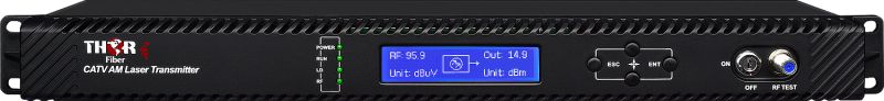
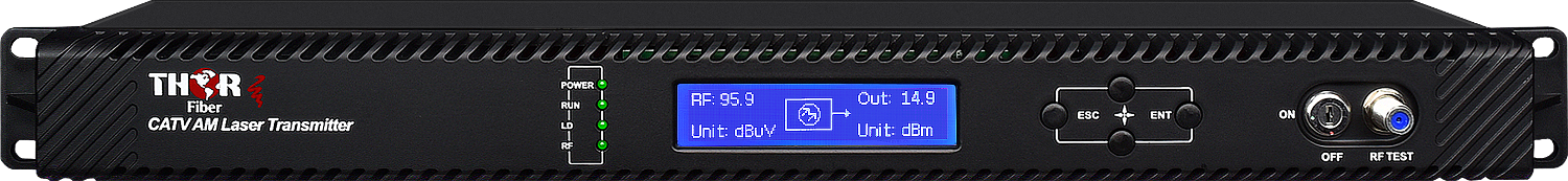
El F-RF-1310-TX-32mW es un transmisor RF por fibra óptica de alta salida diseñado para aplicaciones exigentes que requieren alcance extendido y grandes redes de distribución óptica. Cubre todo el espectro RF de 45-1000 MHz, permitiendo el transporte de lineups completos CATV y servicios RF sobre infraestructura de fibra óptica.
Esta unidad soporta una amplia gama de tipos de modulación, incluyendo RF analógico (NTSC / PAL), QAM digital (J.83B), alimentaciones de antena ATSC, ATSC 8VSB, ATSC 3.0 y otras señales RF dentro de la banda. Todos los servicios se transportan simultáneamente sobre un único enlace óptico, preservando la calidad del canal a largas distancias.
Construido con un láser DFB de alta linealidad y avanzado Control Automático de Ganancia (AGC), este transmisor está optimizado para cargas densas de canales y alto rendimiento MER, ideal para entornos RF digitales modernos.
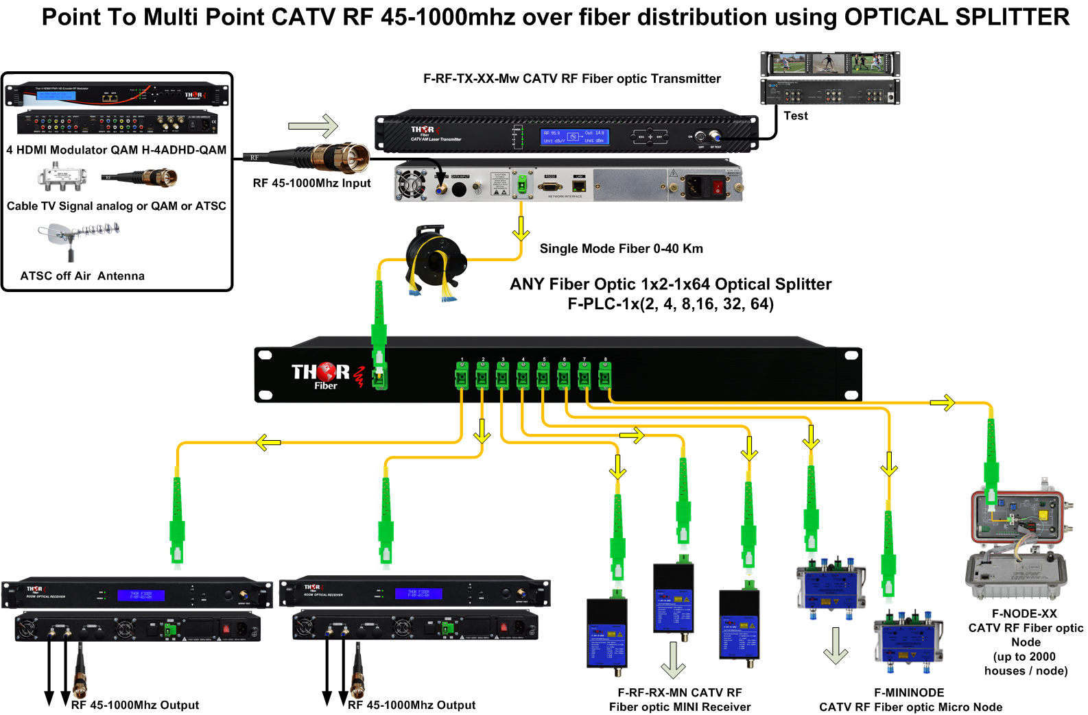
Con una potente salida óptica de 32 mW, este transmisor está diseñado para redes ópticas pasivas de alta relación de división, soportando configuraciones como:
Esto lo convierte en una solución excelente para sistemas de superposición RF FTTH, grandes propiedades hoteleras, estadios, bases militares y distribución CATV empresarial por fibra.
El transmisor de 32 mW está diseñado para redes RF grandes y complejas, incluyendo:
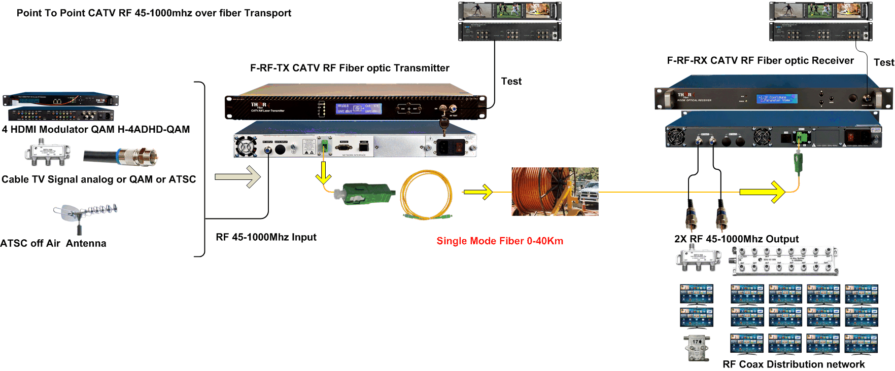
Este transmisor se integra perfectamente con equipos de cabecera RF como moduladores QAM y ATSC, alimentaciones de antena y fuentes CATV. Puede desplegarse con divisores ópticos y receptores para crear redes de distribución RF escalables y de baja pérdida.
| Modelo | F-RF-1310-TX-32mW |
| Longitud de Onda | 1310nm |
| Potencia Óptica | 32mW |
| Rango de Frecuencia | 45-1000 MHz |
| Señales Soportadas | NTSC, PAL, QAM J.83B, ATSC, ATSC 3.0, 8VSB |
| Láser | DFB de Alta Linealidad |
Permite grandes divisiones ópticas y alcance extendido, reduciendo la necesidad de amplificación y simplificando el diseño de la red.
Explore soluciones relacionadas: Sistemas RF por Fibra | Soluciones CATV RF | Moduladores RF
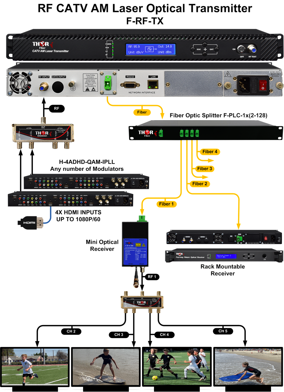
Ejemplo de flujo de señal: fuentes HDMI entran a un modulador Thor, la salida RF alimenta un transmisor óptico RF, la fibra se divide usando divisores PLC, y múltiples receptores ópticos RF convierten la señal de nuevo a coaxial para televisores o amplificadores RF locales.


El transmisor puede utilizarse con cualquier receptor óptico RF Thor Fiber.
- Salida óptica de 32 mW desde sistema láser controlado por retroalimentación del sensor
- Transporta toda la banda 45-1000 MHz incluso con lineups completos de canales
- Crea "Rupturas de Fibra" de alta seguridad para eliminar el camino de retorno de señal coaxial
- Control Automático de Ganancia (AGC) gestiona el nivel RF sin necesidad de ajuste
- Compatible con todos los sistemas receptores ópticos RFoG CATV de Thor
NOTA IMPORTANTE*** (Es muy importante conectar nuestra unidad con un conector SC/APC - Pulido Angular para evitar reflexiones de luz.)
Si su fibra está terminada con conector plano SC, ST, FC/PC, debe usar un jumper óptico de tipo PC a SC/APC para una conversión adecuada.
Están disponibles los siguientes transmisores CATV RF por fibra óptica. Puede ver todos los modelos aquí: Transmisores CATV RF por Fibra
The Thor F-PLC passive fiber optic splitter with SC/APC connectors is an ideal accessory for CATV RF optical transmitters, allowing one optical signal to be split and routed to multiple locations over fiber. Available in 1x2 to 1x64 versions, it is perfect for RF over fiber distribution systems in hotels, campuses, apartment buildings, and other multi-location installations.
Learn more about Thor F-PLC Splitters →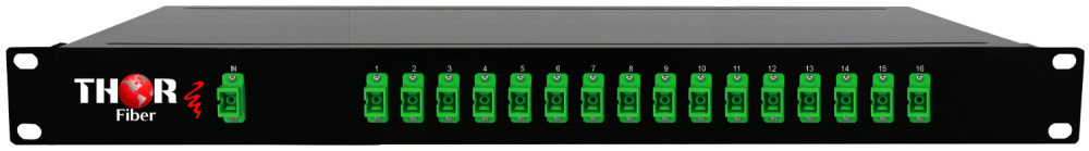
| *Todas las especificaciónes están sujetas a cambios sin previo aviso | |||
|
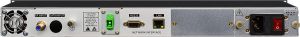
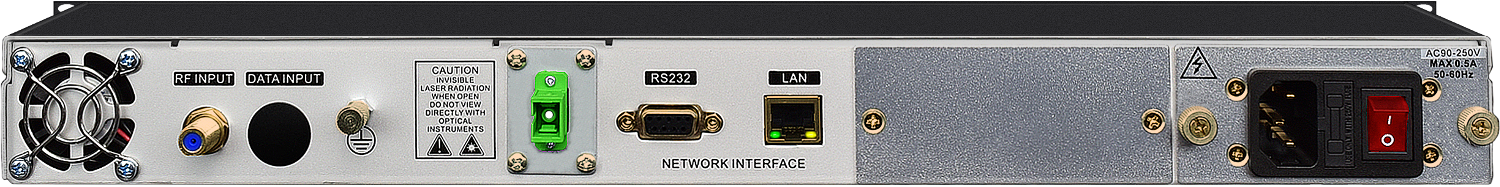
1x conector Tipo-F - 75 Ohmios |
||
|
1310nm | ||
|
< 1 MHz FWHM | ||
|
>20 dB XP | ||
|
< -160 dB/Hz | ||
|
32 mW | ||
|
>55 dB | ||
|
SC/APC - Pulido Angular NOTA IMPORTANTE*** (Es muy importante conectar nuestra unidad con un conector SC/APC - Pulido Angular para evitar reflexiones de luz.) Si su fibra está terminada con conector plano SC, ST, FC/PC, debe usar un jumper óptico de tipo PC a SC/APC para una conversión adecuada. |
||
|
11-29 dBmV gestionado por AGC | ||
|
<+/- 0.75 45 - 862 MHz | ||
|
>17 dBm | ||
|
>50 dB a 10 km de fibra | ||
|
< -63 dB | ||
|
< -57 dB | ||
|
19 x 10 x 1.75 pulgadas | ||
|
2.5 kg | ||
|
0 - 45 °C | ||
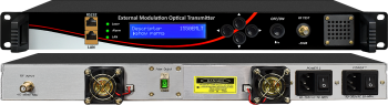 Transmisor RF CATV Modulado Externamente 1550nm - CATV Analógico, QAM o ATSC por Fibra
Transmisor óptico modulado externamente DWDM 1550nm, solución ideal para RF analógica o digital QAM/ATSC de 45-1000 MHz por fibra monomodo. Mejor dispersión y estabilidad que transmisores internos 1550nm. Perfecto para distancias superiores a 30 km.
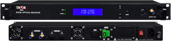 Receptor de Fibra Óptica CATV RF - Alta Potencia RF - Para Montaje en Rack
Receptor de fibra óptica CATV para transportar señales RF en el rango de 40-870 MHz. La unidad puede aceptar señales ópticas en todas las bandas.
 EN
EN


