GPS Over Fiber, Optical RF Transport System
(This unit has been replaced by the F-4GPS-TX-WE/RM - 4 GPS signals over fiber TX/RX with an TX outdoor waterproof enclosure )
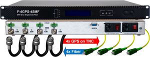
RX - F-4GPS-RX-RM

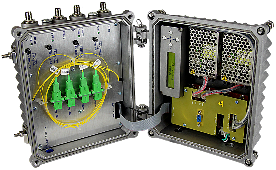
RX - F-4GPS-TX-WE

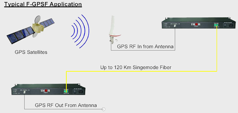
The F-GPS GPS over fiber system is a transmitter and receiver pair used to transmit the RF Carrier signal from a GPS antenna to a remote location up to 10 Km. There are many advantages to converting the GPS Carrier to an optical signal for GPS over fiber. Fiber Optic cable is much less expensive than low loss coaxial cable used for RF signals. It is also much smaller and easier to work with. Optical signals are not affected by RF interference, therefore this system can be used to transport a GPS signal over fiber through a noisy RF environment. The F-GPSF can also be used to transport the GPS signal over fiber from a single GPS antenna to a multitude of locations throughout a building, aircraft, or ship.
This Fiber Optic GPS Antenna Link is a complete system which allows us to convert the GPS Carrier from RF to Light, transmit it up to 20 Kilometers if need be then reconvert it to RF to be received by the GPS Receiver.
Global positioning systems (GPS), used for navigation, relies on signals from satellites in a geosynchronous orbit around the earth. This synchronization is required for personal communications systems (PCS) such as cellular telephones. PCS base station signals using fiber optic transmitters and receivers experience low loss and high quality. In addition, smaller, less expensive power amplifiers can be mounted to the tower reducing transmission losses and system cost. Fiber's dielectric properties also reduce damage from lightning strikes at PCS base stations. Fiber optic L-Band, GPS links can also be used as an outside repeater in shopping malls, tunnels, and subways where PCS signals are non-existent or extremely weak, allowing L-Band satellite transport.
Thor Fiber F-GPS systems are available to support the remote location of industrial GPS antennas. These kits are assembled and tuned to the unique requirements of each application. Thor GPS over fiber systems are a solution for the distance limitation between maritime or government GPS antennas and radio signal receiver equipment. Typically any sensor equipment or tuning hardware such as universal time receivers or GPS navigation gear must be installed and located within 100 ft of the antenna system. Most modern industrial type systems require antennas with a clear view of the horizon to function properly. In the case of large ocean going vessels, underground military installations, or large buildings or structures; it can be a challenge to install GPS equipment within 100 ft of a suitable antenna location. Thor solves this problem by extending the distance to over 20 miles by converting the GPS signal from the antenna from coax to fiber optic cable. F-GPS systems are available in a variety of form factors and can be custom tuned to individual users applications.
The four channel four fiber configuration pictured above is useful for service providers such as cellular network operators wishing to eliminate down time in cell towers. This system can guarantee up-time by providing a signal from up to four independent antennas over four independent fiber optic cables. Since each optical transmitter and receiver are isolated circuits inside the same enclose, it will take a minimum of at least four hardware failures to cause the GPS link to fail. An easy to read front panel LED screen displays signal power from all four circuits; and simple "on - off" LED indicators illuminate to show that the link is functional.

 ES
ES


