2 Satellite LBand + 1 CATV QAM / ATSC RF over fiber Receiver

F-SattGalaxy-TX/RX-3
Qty: 0
Price: $ 2,495.00
Availability: In stock Condition: new
Shipping: starting at $22.00 Warranty: 2 Yrs
Quantity:
add to basket
ask about product
send request
Description Features Drawings Model Selection Specification Q&A Support

Description

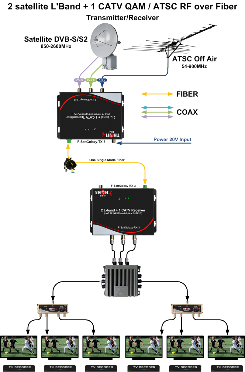
Thor Fiber MDU Satellite over Fiber - Optical Transmitter F-SattGalaxy-TX-3 has 3 independent RF inputs, converts each satellite signal from a quad or quatro LNB, and also terrestrial off-air TV signal via antenna array in a single unit to transmit over one singlemode fiber.
Thor Optical MDU Satellite Receiver F-SattGalaxy-RX converts the optical signal back to the original 2 satellite signals and the third terrestrial off-air TV signal injected on the TX.
Off Air TV / Radio signals like ATSC, Analog NTSC, DVB-T, or ISDB-T, DVB-C QAM annex A/B or RF FM Radio can be used in the 3rd RF port for transmission.
Transmitter and receiver are using a built-in optical Wavelength Division Multiplexing (CWDM) system that uses multiple lasers for carrying signals inside one optical fiber. The built-in CWDM multiplexer enables high-quality transmission using 5 wavelengths (VL: 1510nm, HL:1530nm, VH: 1550nm, HH: 157nm, Ter 1590nm)
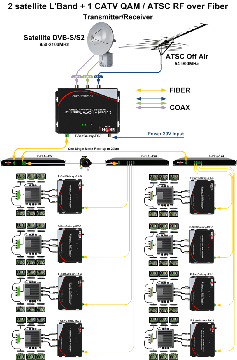
The F-SattGalaxy transmitter provides high optical output power that allows for the distribution of the signals for up to 32 optical receivers located within a radius of 10 kilometers. The exact number of receiving points and the maximum transmission range can be calculated using optical power budget methods. These are model specific for output power and must be ordered as such.
Both the transmitter and receiver use angle polish connector SC/APC  to eliminate any reflections creating a cleaner signal connection.
Point to Point or Point to Multipoint 1x4, 1x8, 1x16, and 1x32 systems are available, it sends the RF from multiple antennas or LNB's to the SWiM switch, eliminating the need for long coax runs, and it is especially beneficial in locations where the Dish and SWiM Switch are far from each other.

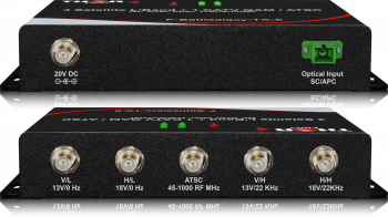
  • The Transmitter has 3 separate RF inputs "F type connectors"
  • Each input generates the specific voltage needed for satellite LNB. 13V, 18V, 13V+22Khz, 18V+22Khz, and 0V for the standard off air antenna
  • Each satellite input supports 950Mhz  to 2150Mhz
  • The terrestrial CATV ATSC / QAM RF input supports 47-900Mhz
  • RF input level needs to be 65-85 dBµV : (5-25dbmv) : ( - 43.75  dBm 75Ω to  - 23.75 dBm 75Ω )
  • Point to point transport applications or point to multipoint up to 1x32 available, perfect for MDU applications.
  • ***Optical output power is a model dependent
  • Great for DirectTV or Dish Network over fiber distribution solution
  • Works with any RF terrestrial Antenna
  • Works with any SWiM Switch


Features

  • One single mode optical cable instead of 5- or 9-cable coaxial trunk
  • Single-mode technology (will not work with multimode fiber)
  • The use of a typical Single or Dual LNB's allows for much easier dish alignment that in the case of an LNB with direct optical output
  • In contrast to competitive solutions, the optical transmitter does not have to be mounted close to the antenna / dish
  • Distribution of the signals to up to 32 optical receivers located within a radius of 10 kilometers (the exact number of the receiving points and the maximum transmission range can be calculated using optical power budget methods);
  • Each receiving point with receiver/converter and a multi-switch or several multi switches creates a local RF distribution system (in total, the number of outlets/subscribers may exceed one thousand).
  • Excellent 1x32 MDU L-band distribution solution
  • Easy to mount on a wall (compact units)
  • Built-in highly efficient Automatic Gain Control (AGC) ensuring a stable level of output signals;
  • Diagnostic LED indicators provide information on operation status and input signal level.
  • Perfect solution for long distance RF extension, ideal for places where standard COAX distribution is too far, or too congested.


Drawings

Model Selection

Ordering Information

F-SattGalaxy-TX/RX- 3  2 L-band and CATV RF Point to Point Transmitter Receiver kit ( The TX  optical power is a balance to support 1 receiver )

F-SattGalaxy-TX/RX- 3-1X4  ( 1 Transmitter + 4 Receivers + 1x4 Optical splitter kit)  2 L-band and CATV RF Point to 4 Multipoint Transmitter Receivers kit  ( The TX  optical power is a balance to support up to 4 receivers )

F-SattGalaxy-TX/RX- 3-1X8  ( 1 Transmitter + 8 Receivers + 1x8 Optical splitter kit)  2 L-band and CATV RF Point to 8 Multipoint Transmitter Receivers kit  ( The TX  optical power is a balance to support up to 8 receivers )

F-SattGalaxy-TX/RX- 3-1X16  ( 1 Transmitter + 16 Receivers + 1x16 Optical splitter kit)  2 L-band and CATV RF Point to 16 Multipoint Transmitter Receivers kit  ( The TX  optical power is a balance to support up to 16 receivers )

F-SattGalaxy-TX/RX- 3-1X32  ( 1 Transmitter + 32 Receivers + 1x32 Optical splitter kit)  2 L-band and CATV RF Point to 32 Multipoint Transmitter Receivers kit  ( The TX  optical power is a balance to support up to 32 receivers )

Specification

 
Name   2 Satellite L-Band + 1 CATV QAM / ATSC  RF over fiber Transmitter
Part Number F-SattGalaxy-TX-3 (Transmitter)
Input frequency range [MHz] 47-2150
RF inputs - signal level [dBμV] 75±10
Power transmission for LNB 13/18 V (350 mA)
Impedance [Ω] 75
Optical output power [dBm]   +2 to +10 Model Dependent
SAT/DVB-T transmission window III (VL: 1510 nm, HL: 1530 nm, VH+Terr: 1550 nm, HH: 1570 nm)
RF connectors F-Type
Optical connector SC/APC
Supply voltage [VDC] 20
Power consumption [W] < 15
Operating temperature range [ºC] -10...+40
Dimensions [mm] / In 195x128x40 / 7.7"x 5" x 1.57"
Name   2 satellite L-Band + 1 CATV QAM / ATSC  RF over fiber Receiver
Part Number F-SattGalaxy-RX-3 (RECEIVER)
Output frequency range [MHz 47-2150
RF Output - signal level [dBμV] 75±10 AGC
Input signal level (optical) [dBm]  -14 ... + 3 (AGC range: -7...2)
Impedance [Ω] 75
AGC efficiency [dB]   ±1
SAT/DVB-T transmission CWDM wavelengths III (VL: 1510 nm, HL: 1530 nm, VH+Terr: 1550 nm, HH: 1570 nm)
RF connectors F-Type
Optical connector SC/APC
Supply voltage [VDC] 20
Power consumption [W] < 10
Operating temperature range [ºC] -10...+40
Dimensions [mm] / In 195x128x40mm  / 7.7" x 5" x 1.57"

Question and Answers

Answer:
We do have several devices which possibly can meet your application
 
 
Stand alone F-LBAND-TX/RX
Back1.png
 
 
We do have also Integrated 4ch or 6 channel L-BAND, mixed optical on CWDM
 
F-LB41-CWDM-TX/RX
 
4 Ch L-Band  Satellite Over single Fiber Extender  Transmitter and Receiver 45-3000Mhz -CWDM
 
F-LB61-CWDM-TX/RX
 
 
6 Ch L-Band Satellite Over single Fiber Extender Transmitter and Receiver 54-3000Mhz -CWDM
 
We do have also portable 4ch units L'Band
F-SattGalaxy-TX/RX-5
 
 
4 x Satellite L-Band LNB's + 1 CATV QAM / ATSC  RF over 1 fiber Transmitter F-SattGalaxy-TXRX-5 MDU Distribusion Solution
 
 
Please review the products and let me know if you have any questions
We do not have a chassis system, but you can possibly use multiple 1,4, 6 channel units instead.
Please let me know if any of them would work for you.
Answer:

1) For the bi-directional RF over fiber, you could possibly use 2 of F-L-band-TxRx and use them in reverse over 2 fibers.

F-L-band-TxRx
The frequency range is 45-2600mhz
You  would need to have 2 TX/RX sets to make it bi-directional and use
2 single mode fibers.

------------

we do not carry any duplexers that would be needed, but there are widely accessible options. 
You would need to find out the forward frequency and return frequency; a duplexer acts as a filter for a specific band and passes the other.
 

The exact frequency bands can vary between different generations of cellular technology (2G, 3G, 4G, 5G), and different carriers might use different bands 

Here are some commonly used frequency bands in the United States for various cellular technologies:

  1. 2G (GSM):

    • GSM 850: 824-849 MHz (Uplink), 869-894 MHz (Downlink)
    • GSM 1900: 1850-1910 MHz (Uplink), 1930-1990 MHz (Downlink)
  2. 3G (UMTS):

    • UMTS Band II (1900 MHz): 1850-1910 MHz (Uplink), 1930-1990 MHz (Downlink)
    • UMTS Band IV (AWS): 1710-1755 MHz (Uplink), 2110-2155 MHz (Downlink)
  3. 4G (LTE):

    • LTE Band 2 (1900 MHz): 1850-1910 MHz (Uplink), 1930-1990 MHz (Downlink)
    • LTE Band 4 (AWS): 1710-1755 MHz (Uplink), 2110-2155 MHz (Downlink)
    • LTE Band 12/17 (Lower 700 MHz): 699-716 MHz (Uplink), 729-746 MHz (Downlink)
    • LTE Band 13 (Upper 700 MHz): 777-787 MHz (Uplink), 746-756 MHz (Downlink)
  4. 5G (NR):

    • 5G NR n71 (600 MHz): 663-698 MHz (Uplink), 617-652 MHz (Downlink)
    • 5G NR n77 (3.7 GHz): 3300-4200 MHz (Uplink), 3300-4200 MHz (Downlink)

These are general frequency ranges, and specific carriers may use variations within these bands. It's essential to check with the specific carrier and their allocated spectrum for the most accurate information. Duplexers for cell phones are designed to work within these frequency bands to enable simultaneous two-way communication.


Similar products:

4 LNB's satellite distribution system for MDU over 1 fiber - DWDM- High Power 4 LNB's satellite distribution system for MDU over 1 fiber - DWDM- High Power

4x Ch L-Band DWDM Transmitter for Satellite TV. Designed for delivery of satellite service to more than 5000 locations, or to be used as a satellite to home LTTH system. Used similarly as many CATV FTTH systems, instead LTTH units transport 4 independent satellite signals off the Dish and mux them into a single fiber. DWDM light spectrum could be amplified by EDFA, this is why we can distribute the

6GHz RF over Fiber 6GHz RF over Fiber

Up to 6GHz Analog Analog RF optical transport - RF over fiber Transmitter / Receiver for for Satcom, GPS, WiMAX, LTE, DAS RF transport applications

Contact Us

Thor Broadcast Sales


Customer Service/ Support