These are simple plug-and-play devices that can be installed in minutes.
Each one of them has different insertion loss; please check the individual units for more information.
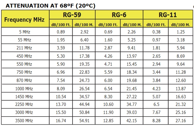
The table below shows the insertion loss in dB per 100 feet for COAX (RJ-59, RG-6, RG-11) depending on the frequency.
It will help to determine the correct RF budget calculation.
MODEL | Picture | Insertion Loss |
H-SP-1x2 1x2 or 2x1 Two-way CATV RF Coax Multiplexers Splitters combiners - portable 5-2100Mhz |
4.5dB | |
H-SP-1x4 1x4 Four-way CATV RF Coax Multiplexers Splitters combiners - portable 5-2100Mhz |
8dB | |
H-SP-1x8 1x8 Eight-way CATV RF Coax Multiplexers Splitters combiners - portable 5-2100Mhz |
11.5dB | |
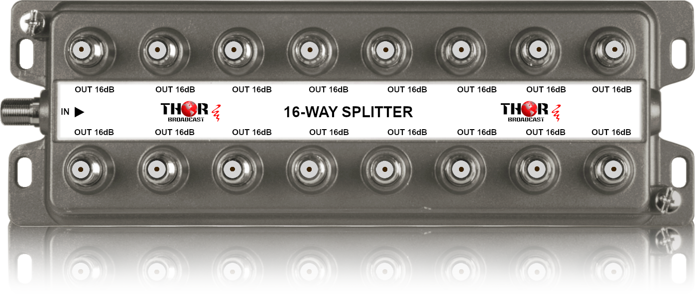
H-SP-1x16 1x6 Sixteen-way CATV RF Coax Multiplexers Splitters combiners - portable 5-1000Mhz |
14.5dB | |
H-SP-1x12-RM 1x12 Twelve-way CATV RF Coax Multiplexers Splitters combiners - 19" Rack Mountable 5-1000Mhz |
12.5dB | |
H-SP-1x24-RM 1x24 or 24 to 1 CATV RF Coax Multiplexers Splitters combiners - 19" Rack-Mountable 5-1000Mhz |
18dB | |
The CATV RF coaxial network can be designed in many different ways, depending on various individual factors, such as:
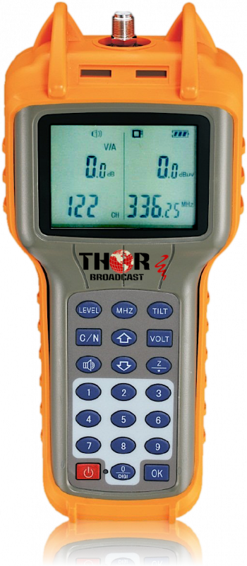
Each splitter has its own insertion loss, which is why the RF Power Meter H-RF-MET is a handy tool for installation and troubleshooting. Here are links to the RF Power Meter and CATV RF Amplifier, in case they are needed for your installation or troubleshooting." Let me know if you want to adjust anything further! |
||
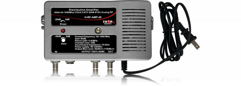
40db RF Amlifier H-AMP-RF-40 |
Features & Specs | ||
---|---|---|
Number of Splits | A number of outputs do this splitter support? | 2,4,8,12,16,24 |
Connector Type | The type of connectors are used on this splitter? | F-Type Female |
Frequency Range | Frequencies supported by this Splitter? |
2,4,8 way Supports 5 to 2100 MHz 12,16,24 way Supports 5 to 1000 MHz |
DC Passing Ports | Number of Ports that will allow DC power through the splitter? | No Ports Power Passing |
Grounding Block | Does this splitter have a grounding point? | Yes |
You can use different techniques to distribute a signal to 20 TVs depending on their locations. The Petit Modulator outputs 30 dBmV RF power. The lowest level a TV can detect is 0 dBmV. Different splitters have different losses, called insertion loss. For example, the H-SP-1x2 has a 4.5 dB loss, the 1x4 has a 7.5 dB loss, the 1x8 has an 11 dB loss, the 1x12 has a 16 dB loss, the 1x16 has a 16 dB loss, and the 1x24 has a 21 dB loss.
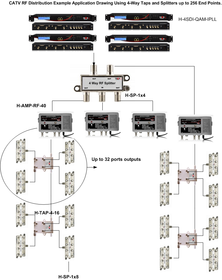
Knowing this, you can use just 1x24 splitters and run individual coax cables, or you can use a combination of splitters and calculate the total loss to ensure it is less than 30 dB. For example, you can use a 1x2 splitter first, then run two coax cables to two 1x16 splitters, or use a 1x4 splitter with four 1x8 splitters. This way, you create zones and save on coaxial cables.
You can also use a combination of splitters and taps. A tap has an input, a drop, and an output. It has a small insertion loss between the input and output, and the drop is dedicated for TV connections. Taps allow cascading, which means you can use a 1x2 tap for each TV and cascade the output to another tap. This method allows cascading and saves on the amount of coaxial cables you will use.
The most important thing is to ensure you do not lose more than 30 dB. If you need more than 30 dB, you would need to use amplifiers in your system.
link to the RF amlifiers
https://thorbroadcast.com/product/40db-bi-directional-distribution-amplifier-54-1000mhz-coax-catv-qam-atsc-analog-8230.html
Cable CATV RF QAM, ATSC, Analog NTSC PAL Tester/Digital Signal Level Meter
The handheld optical power meter is a fiber optic test instrument. Fiber-optic installations require end-to-end optical loss measurements. The meter can measure eight standard WDM and CWDM wavelengths: 850nm, 980nm, 1300nm, 1310nm, 1490nm, 1550nm, 1625nm, and 1650nm. It has universal ST, FC, and SC interface connectors, making it a very convenient and universal tool.