| Availability: | In stock | Condition: | new |
|
| Shipping: | starting at $0.00 | Warranty: | 2 |
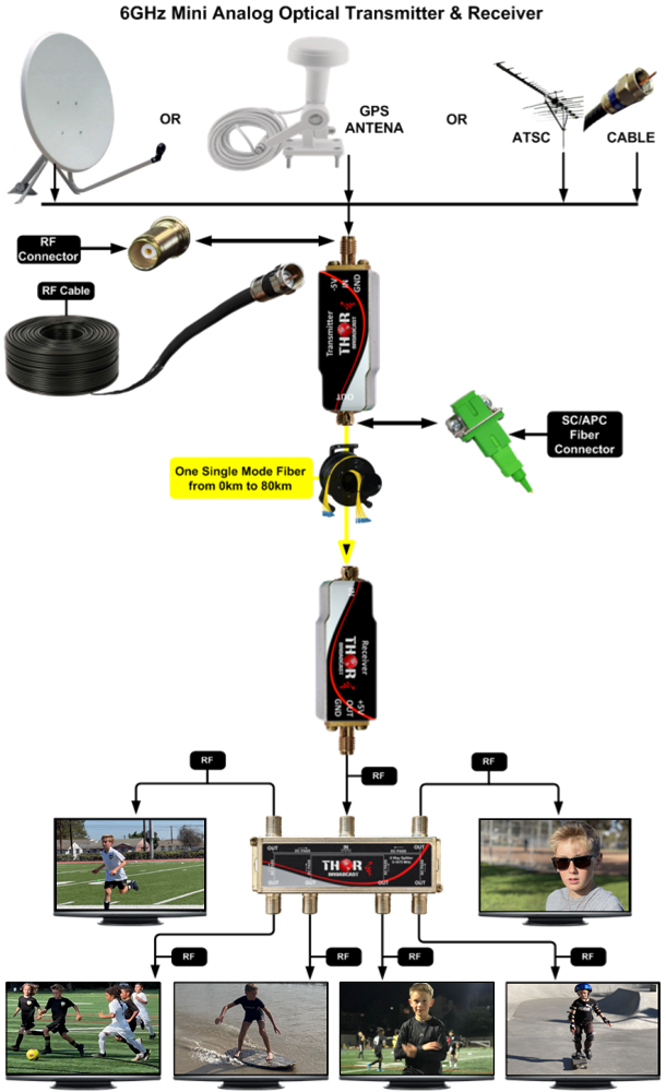
Analog RFoF optical Transmitter is used to convert RF signals to optical signals that can be sent and carried over long distances of fiber optic cable.
The Optical Receiver converts them back to an RF signal. The two units are connected through 1 single mode fiber up to 40Km.
RF over Fiber modules (RFoF) are commonly used in L-band, S-band satellite, radio telescopes, RF antennas distribution, broadcasting audio, and video, timing synchronization and GPS applications and other telecommunications.
It's very easy and cost effective to extend a signal from any antenna, Modulator or RF instrument, point to point or multipoint to multipoint using fiber optic splitters.
Applications
IMPORTANT NOTE*** (It is very important to interface our unit with the SC/APC - Angle Polished Connector to avoid any light reflections.)
If your fiber is terminated with the SC, ST, or FC/PC flat connector, you need to use an optical jumper from PC type to SC/APC for proper conversion.
F-RFoF-6GHZ-TX RFoF -RF over fiber 6Ghz optical Transmitter
F-RFoF-6GHZ-RX RFoF -RF over fiber 6Ghz optical Receiver
F-RFoF-6GHZ-LNA-TX/RX RFoF - RF over fiber 6Ghz optical Transmitter Receiver Kit with LNA (Low Noice Amlifier)
The base models operate at 1310 nm.
We can supply CWDM wavelengths upon request—special order, quote required.
For CWDM variants, the part number ends with -XX indicating the wavelength (e.g., -1510, -1530, -1550, -1570, -1590, -1610 nm). -Examle : F-RFoF-6GHZ-LNA-TX/RX-1510nm
IMPORTANT NOTE*** (It is very important to interface our unit with the FC/APC - Angle Polished Connector to avoid any light reflections.)
If your fiber is terminated with the SC, ST, or FC/PC flat connector, you need to use an optical jumper from PC type to FC/APC for proper conversion.
|
Parameter |
Symbol |
Condition |
Min. |
Max. |
Unit |
|
Operating Case Temperature |
Topr |
|
-20 |
+70 |
deg C |
|
Storage Temperature |
Tstg |
|
-40 |
+85 |
deg C |
|
DC Operating Voltage |
Vd |
+5V Pin |
+4.7 |
+5.5 |
V |
|
RF Input Power |
Prf |
Without LNA |
-- |
20 |
dBm |
|
With LNA |
-- |
15 |
|||
|
Output Optical Power |
Ps |
CW |
-- |
12 |
mW |
|
Relative Humidity |
Hr |
|
-- |
95 |
% |
|
Pressure |
Pr |
|
86 |
106 |
kPa |
|
ESD |
|
Human body model |
|
Class 1A |
|
| Note: Operation beyond these absolute maximum conditions may degrade device performance, lead to device failure, shorten lifetime, and invalidate the device warranty. | |||||
Typical Specification
|
Parameter |
Test Condition |
MIN. |
TYP. |
MAX. |
Unit |
|
|
Frequency Range |
TSC |
0.01 ~ 3 |
GHz |
|||
|
TCC |
0.01 ~ 6 |
|||||
|
Optical Wavelength |
CWDM |
Optional |
nm |
|||
|
Gain (2) |
TSC |
Tx with LNA, Rx with LNA |
6 |
14 |
-- |
dB |
|
Tx with LNA Rx without LNA |
-11 |
-3 |
-- |
|||
|
Tx without LNA, Rx with LNA |
-11 |
-3 |
-- |
|||
|
Tx without LNA, Rx without LNA |
-28 |
-24 |
-- |
|||
|
TCC |
Tx without LNA Rx with LNA |
-11 |
-3 |
-- |
||
|
Tx without LNA, Rx without LNA |
-30 |
-26 |
-- |
|||
|
Ripple of Passband |
TSC |
100M~3GHz, 1270nm~1370nm |
-- |
+/-1.5 |
+/-2.2 |
dB |
|
100M~3GHz, 1530nm and 1550nm |
-- |
+/-2.5 |
+/-3.0 |
|||
|
TCC |
100M~6GHz, 1270nm~1370nm |
-- |
+/-1.5 |
+/-2.2 |
||
|
100M~6GHz, 1530nm and 1550nm |
-- |
+/-2.5 |
+/-3.0 |
|||
|
Output Optical Power |
+25 deg C |
-- |
9 |
-- |
dBm |
|
|
RF Return loss (50 Ohm) |
TSC |
10MHz ~ 3GHz, RF Input |
-- |
-10 |
-5 |
dB |
|
TCC |
10MHz ~ 6GHz, RF Input |
-- |
-10 |
-5 |
||
|
Input P-1dB?2? |
TSC |
With LNA, 1.5GHz |
-- |
0 |
-- |
dBm |
|
Without LNA, 1.5GHz |
-- |
17 |
-- |
|||
|
TCC |
Without LNA, 3GHz |
|
17 |
|
||
|
SFDR(2) |
TSC |
1.5GHz |
102 |
115 |
-- |
dB- Hz2/3 |
|
TCC |
3GHz |
102 |
113 |
-- |
||
|
Input IP3(2) |
TSC |
With LNA, 1.5GHz |
4 |
9 |
-- |
dBm |
|
Without LNA, 1.5GHz |
25 |
33 |
-- |
|||
|
TCC |
Without LNA, 3GHz |
21 |
33 |
-- |
||
|
Noise Figure (2) |
TSC |
With LNA, 1.5GHz, 1270nm ~1370nm |
-- |
18 |
25 |
dB |
|
With LNA, 1.5GHz, 1530nm and 1550nm |
-- |
20 |
26 |
|||
|
Without LNA, 1.5GHz, 1270nm~1370nm |
-- |
32 |
40 |
|||
|
Without LNA, 1.5GHz 1530nm and 1550nm |
-- |
35 |
42 |
|||
|
TCC |
Without LNA, 3GHz, 1270nm ~1370nm |
-- |
32 |
42 |
||
|
Without LNA, 3GHz, 1530nm and 1550nm |
-- |
38 |
45 |
|||
|
Operating Current |
With LNA, TSC |
-- |
145 |
200 |
mA |
|
|
Without LNA, TSC/TCC |
-- |
55 |
100 |
|||
|
Operating Voltage |
+5V pin |
+4.8 |
+5 |
+5.2 |
VDC |
|
|
Bias-T Voltage |
Through the RF SMA connector |
+4.8 |
+5 |
+5.2 |
VDC |
|
|
Bias-T Current Supply |
Through the RF SMA connector |
- |
-- |
200 |
mA |
|
| Note: (1) The lower start frequency, such as 9kHz, can be customized (without LNA only); (2) Test with optical receiver (see the picture below), and the fiber is 1-meter SMF-28 fiber. | ||||||
|
Type |
Connector |
|
RF |
SMA (50Ohm), Female |
|
Optical |
FC/APC (1) |
|
Optical Fiber Type |
SMF-28 (Standard) |
|
Power |
EMI Low Pass Filter, Feed Through Capacitor |
Note (1): Other types of optical connectors are available upon request.
|
PIN |
Name |
Direction |
Note |
|
1 |
+5V |
I |
+5V DC Power |
|
2 |
GND |
I |
RF and DC Ground |
|
3 |
OP |
O |
Optical Power Monitor. A power level of +2.2V+/-0.4V indicates normal transmit optical power; otherwise, it indicates abnormal transmit optical power. |
 |
Optical Transmitter
|
OM |
- |
TxC |
xxx |
N |
x |
- |
O |
S |
x |
x |
|
OM: Optical Module |
|
Frequency Range (1): TSC: 10M~3GHz TCC: 10M~6GHz |
Wavelength (2): 127:1270nm 129:1290nm ... 137:1370nm 153:1530nm 155:1550nm |
|
Optical Connector and Fiber Type (3): F FC/APC SM L: LC/APC SM |
|
|
Operating Temperature (4) S: -20 to 70 deg C |
Bias-T: 1: without T: with |
LNA (5): 0: without 1: with |
Note: The lower start frequency, such as 9kHz, is available upon request (without LNA only); (2) Other wavelengths are available upon request; (3) Other types of optical fiber connector are available upon request; (4) Other temperature ranges are available upon request; (5) LNA only supports the TSC frequency band for the time being.
|
Parameter |
Symbol |
Condition |
Min. |
Max. |
Unit |
|
Operating Case Temperature |
Topr |
|
-20 |
+70 |
deg C |
|
Storage Temperature |
Tstg |
|
-40 |
+85 |
deg C |
|
DC Operating Voltage |
Vd |
+5V Pin |
+4.7 |
+5.5 |
V |
|
Saturation Input Optical Power |
Ps |
CW |
-- |
10 |
mW |
|
Relative Humidity |
Hr |
|
-- |
95 |
% |
|
Pressure |
Pr |
|
86 |
106 |
kPa |
|
ESD |
|
Human body model |
|
Class 1A |
|
|
Note: Operation beyond these absolute maximum conditions may degrade device performance, lead to device failure, shorten lifetime, and invalidate the device warranty. |
|||||
|
Parameter |
Test Condition |
MIN. |
TYP. |
MAX. |
Unit |
|
|
Frequency Range |
RSC |
0.01 ~ 3 |
GHz |
|||
|
RCC |
0.01 ~ 6 |
|||||
|
RXC |
0.01 ~ 12 |
|||||
|
Optical Wavelength |
|
800~1650 |
nm |
|||
|
Gain (1) |
RSC |
Tx without amplifier, Rx with amplifier |
-11 |
-3 |
-- |
dB |
|
Tx without amplifier, Rx without amplifier |
-28 |
-24 |
-- |
|||
|
RCC |
Tx without amplifier, Rx with amplifier |
-11 |
-3 |
-- |
||
|
Tx without amplifier Rx without amplifier |
-30 |
-26 |
-- |
|||
|
RXC |
Tx without amplifier, Rx without amplifier |
-30 |
-26 |
-- |
||
|
Ripple of Passband (1)(2) |
RSC |
100MHz ~ 3GHz |
-- |
+/-1.2 |
+/-2 |
dB |
|
RCC |
100MHz ~ 6GHz |
-- |
+/-1.5 |
+/-2.2 |
||
|
RXC |
100MHz ~ 12GHz |
-- |
+/-2.0 |
+/-2.5 |
||
|
Input Optical Power |
+25? |
-- |
-- |
10 |
dBm |
|
|
Back Reflection |
|
-- |
35 |
-- |
dB |
|
|
PD Responsivity |
1310nm |
0.7 |
0.8 |
-- |
mA/mW |
|
|
1550nm |
0.7 |
0.85 |
-- |
|||
|
RF Return loss (50 Ohm) |
RSC |
100MHz ~ 3GHz |
-- |
-12 |
-8 |
dB |
|
RCC |
100MHz ~ 6GHz |
-- |
-10 |
-7 |
||
|
RXC |
100MHz ~ 12GHz |
-- |
-10 |
-5 |
||
|
Operating Current |
With amplifier, RSC/RCC |
-- |
90 |
120 |
mA |
|
|
Without amplifier, RSC/RCC/RXC |
-- |
7 |
10 |
|||
|
Operating Voltage |
+5V pin |
+4.8 |
+5 |
+5.2 |
VDC |
|
| Note: (1) RSC and RCC are tested with Mini optical Tx (see the picture below). RXC is tested with optical Tx, and the fiber is 1-meter SMF-28 fiber. (2) The ripple includes Tx and Rx. | ||||||
|
Type |
Connector |
||
|
RF |
SMA (50Ohm), Female |
||
|
Optical |
FC/APC (1) |
||
|
Optical Fiber Type |
SMF-28 (Standard) |
||
|
Power |
EMI Low Pass Filter, Feed Through Capacitor |
||
| Note (1): Other types of optical connectors are available upon request. | |||
| PIN Function | |||
| ________________________ |
|
________________________ | |
|
PIN |
Name |
Direction |
Note |
|
1 |
+5V |
I |
+5V DC Power |
|
2 |
GND |
I |
GND |
|
3 |
OP |
O |
Received Optical Power Monitor. The voltage of OP is explained below. |
The OP voltage (Vop, unit: V) VS received optical power ( Pop, unit: mW) follows the formula:
Vop? D*Pop
The D factor is defined as the detection factor in V/mW units. The typical range of D is from 0.25 V/mW to 0.5 V/mW. For example, D=0.375 V/mW, the OP voltage (Vop) VS received optical power (Pop) is as shown in the table below:
|
Vop (V) |
Pop (mW) |
|
3.75 |
10 |
|
3.375 |
9 |
|
3 |
8 |
|
2.625 |
7 |
|
2.25 |
6 |
|
1.875 |
5 |
|
... |
... |
|
0 |
0 |
|
The user can input the known optical power Pop and detect the Vop voltage, and then calculate the approximate value of the D factor of an optical receiver using the formula Vop? D*Pop. In this case, the obtained D factor and Vop can be used to estimate the optical power received by the optical receiver in practical applications. Notes:
|
|
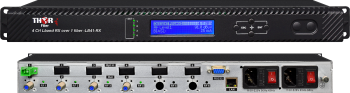 4 Ch L-Band Satellite Over single Fiber Extender Transmitter and Receiver 45-3000Mhz -CWDM
4 CH LNB satellite dish fiber optic transport over single-mode fiber optic cable 4-laser Satellite TV antenna feed over fiber optic transmitter system with internal CWDM optics. Ideal for point-to-point transport or point-to-multipoint up to 32. Most advanced multi-channel satellite distribution system for MDU. Maximum durability with advanced automatic system adjustments to deliver 100% clear HDTV programming with zero signal loss.
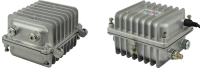 1 L-Band LNB Dish over fiber Extender with Outdoor Enclosure
Satellite RF 1 L-Band over fiber system, complete transmitter and receiver kit for harsh-environment or outdoor installations.
 ES
ES


